Dear all,
as I'm new to this forum, maybe allow me to introduce myself. I've been building R/C cars for over 20 years now but only started with serious modifications and own designs when the Crawler craze (TLT-based) first hit.
I've always had a particular interest in earth-moving machines, particularly graders - from horse-drawn to the most advanced concepts.
I wanted to build one in about 2005 - but I wasn't quite there yet and it remained a rather hopeless CAD model

In the meantime, there are now a number of grader models, often based on simple modifications of the Bruder Grader - I wanted something a bit more substantial with as many functions as possible - without going to the top-of-the-line like the 1:8 O&K in Germany or the CATs I've seen here. Wow!
No mill or lathe or budget for hydraulics obviously meant I had to cut back on something. As I wanted good operation, I threw scale realism pretty much out of the window.
It took a lot of planning, but I dare say that I have achieved my goal of building a relatively affordable grader with basic tools that still performs well.
'll post a few pictures, but if you want to see more, please follow this link to a gallery I have set up, it roughly goes along the build process:
http://flickr.com/gp/22070130@N07/13BERN
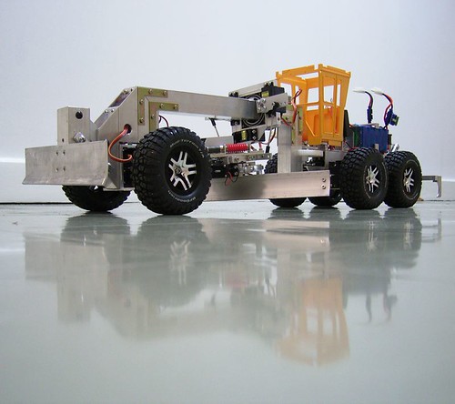
The grader uses the cab and bonnet (which will be extended eventually) of the Bruder toy. The machine itself is considerably larger, though. In 1:14.5 it is just within the 3m width-limit that makes it street legal in the EU without special permit. In 1:Tamiya, it has a few inches to spare and fits with the trucks quite nicely, I think.
 http://www.flickr.com/photos/2207013...57626598857828
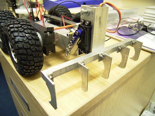
The construction is based around aluminium profiles (as is obvious). As power tools, only a drill press, a mitre saw and a jigsaw were used. Everything is bolted together, mainly with stainless M3 cylinder head screws. The main frame is held by stainless M3 bolts with hexagonal heads in the hope that this gives a little bit of realism. The design is pretty basic - lots of right angles and M3 is of course not scale - but there's no way I will tap all these threads in M2
Drive is through four RB35 motors. Wheels and tires are from the Traxxas Slash 4x4 and offer a small rim diameter on the outside, but a large one on the inside, allowing more room. Initially I had planned 6x6, but couldn't do driven front wheels with wheel-lean and so went for non-driven front wheels with wheel lean.
I plan to cover the rims eventually as it looks too much like a sports car, but I am not quite sure how to do that - yet.
All functions are operated by electric motors, either in servos or as gear motors. I opted for the cheap MG995 servos. Their performance issues are not so much an problem for a slow machine as they are for airplanes. But the looseness in the gears is problematic. The 996R is much better, I hear. Might upgrade eventually.
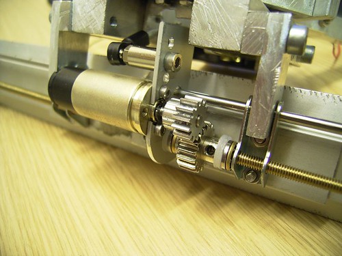
I converted one servo to a spindle drive (to tilt the moldboard) and used a gear motor with a pinion-pinion transmission to move the moldboard sideways: The driven pinion has an M4 thread tapped into it and drives the brass M4 threaded rod. Works nicely and seems robust enough to cope with dirt - but this is clearly not ideal, so I will have to think about some kind of shielding.
 http://www.flickr.com/photos/2207013...7626598857828/
The three servos controlling the drawbar position are operated through "hydraulic modules". These make the stick position proportional to the servos' speed, not their angle.
All in all, the following functions are integrated:
drive (RB35 ESC)
steer (servo)
wheel lean (servo)
articulation (modified servo, continuous rotation with secondary gear drive)
moldboard angle (modified servo, continuous rotation with spindle drive)
moldboard sideshift (gear motor with spindle drive)
drawbar left height (servo, hydraulic module)
drawbar right height (servo, hydraulic module)
drawbar horizontal position (servo, hydraulic module)
rotation of these three servos around the centre axis (gear motor with hollow gear)
circle rotation (gear motor with worm drive, infinite rotation of circle through four-pole stereo plug)
front blade (servo arm is lever)
rear scarifier (servo arm is lever)
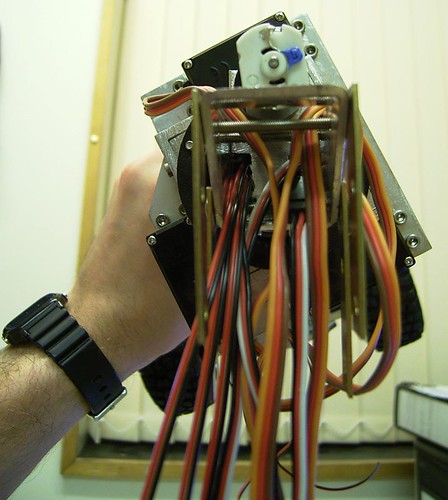
That's 13 functions, and assorted cables...
 http://www.flickr.com/photos/2207013...7626598857828/
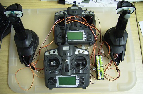
Everything is controlled via two modified Turnigy 9x 2.4GHz transmitters, these are 7.5 channel transmitters. This means I have one proportional and two on-off channels left). Currently I run the standard software, but calibrated the custom sticks I use. They started their existence as Cyborg V.1 flightsticks for flight simulators. Added onto those are Playstation thumbsticks, partly modified to give friction (non-returning) operation.
 http://www.flickr.com/photos/2207013...7626598857828/
Also modified are the two remaining sticks of the original transmitter. Their vertical axes are the only ones left operational - one has been modified with parts from the other transmitter to give friction operation. This allows easy operation of the two attachments. Driving the machine happens with the left flightstick, so the right hand is free to operate the attachments.
 http://www.flickr.com/photos/2207013...7626598857828/
The Bruder model is a slightly older model, but I went for the new user interface of the M-series, hence the crossbreed of flightsticks with thumbsticks
This comes closest to the original user interface, without the use of foot pedals or advanced electronics. Here's a video of the real deal:
http://www.youtube.com/watch?v=2NkATUsfK7Y
As it's pretty much done, apart from improving some areas, I cannot provide the joy of a build thread, but if you have any questions, I would be very happy to answer your questions - we need more graders on the parcours

Best wishes
Jens