In an earlier article I wrote describing how I built a 3D printed lowboy trailer there was some discussion about the strength limits of such a model versus the conventional all metal designs. This article can be found at
http://www.rctruckandconstruction.co...ad.php?t=13235
Furyfan made the suggestion of embedding a piece of metal into the plastic during the printing process to strengthen the gooseneck. I had not thought of this before. In fact I don't think I've even heard of any one else doing this, but I started thinking about the possibilities. I knew that my printer and slicer could be set to to pause/resume during a print. This was primarily, I had always assumed, to enable the changing of filament during a print to a different type or color, but had never used it. So I started doing a bit of research. I determined that with a lot of care as to selecting metal thickness, layer heights, pause layer selection and placement in the gcode it should be possible to do this. So I decided to experiment and see if parts could be made stronger this way.
I also thought that if I was going to try this I might as well also try some experiments with just changing some of the settings configurations to see what affect on overall strength they could have. I came up with five different configurations that would be tested.
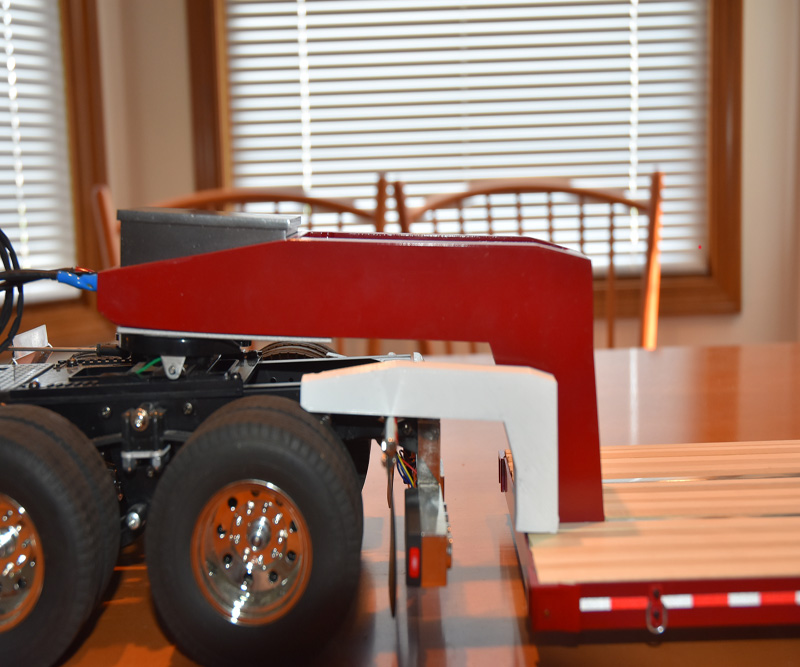
I decided that all five test samples would have the same basic shape, namely that of the gooseneck on my original model. Now I was not about to spend the time and amount of plastic to create five sample the same size as the original. I decided to to make prints of only one side of the gooseneck at half the size of the original model. Here is a photo showing the size of one of the test samples to the original model.
[img]
[/img]
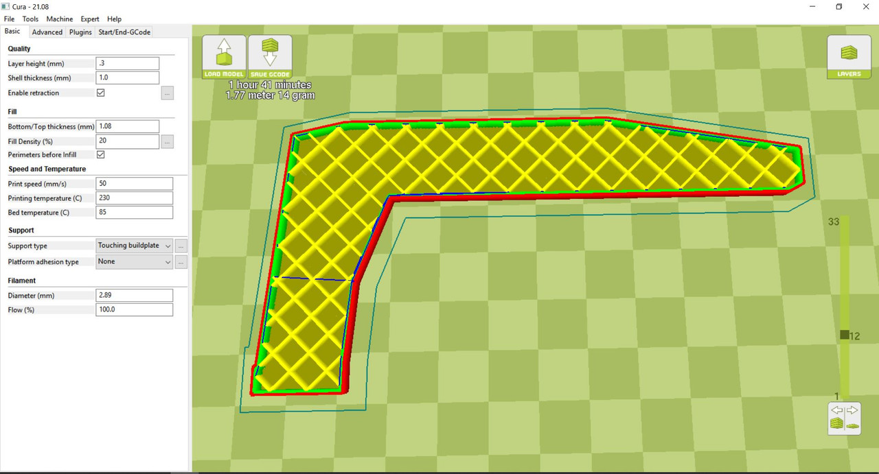
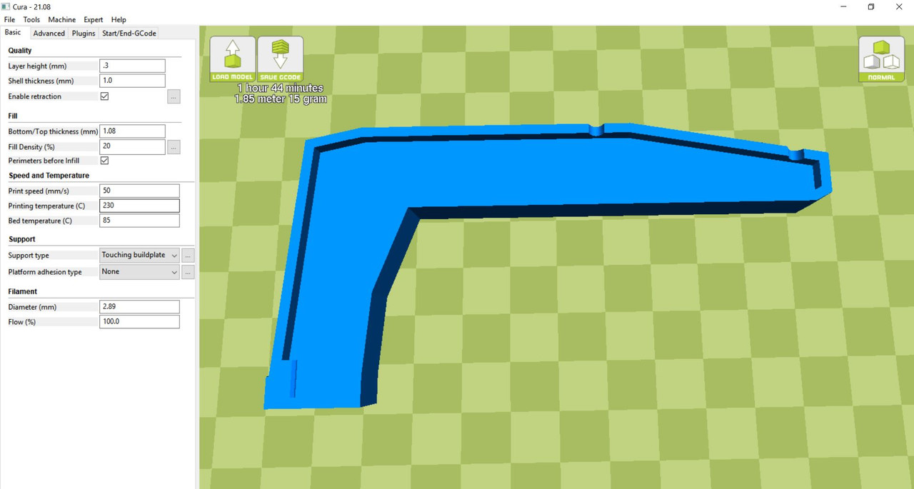
Sample A: This would be the base line test sample. It would be printed with the same settings as I used in my lowboy build. 0.3 mm layer height, 1 mm skin thickness and 20% infill. I used a filament called nGen. This is the primary filament I use today for almost all my prints. I love this stuff. It is as strong, if not stronger than ABS, prints smoother, doesn't shrink like ABS, doesn't have the hot plastic stink that ABS does and while it needs a heated bed for printing it doesn't have to be near as hot.
[img]
[/img]
Sample B: This would have the same slicer settings as A but would be set up for a piece of aluminum metal following the shape of the gooseneck to be inserted. I'll discuss this in more detail later.
[img]
[/img]
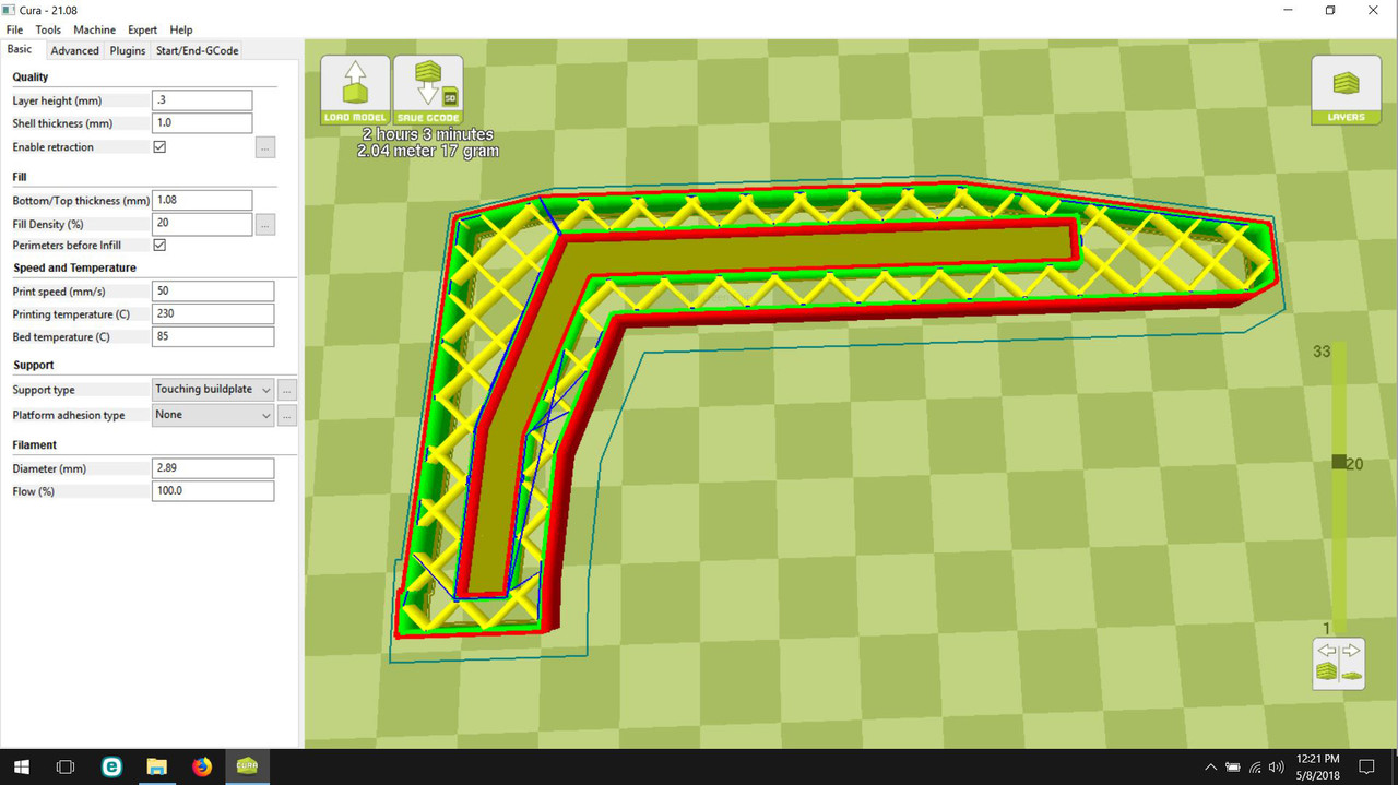
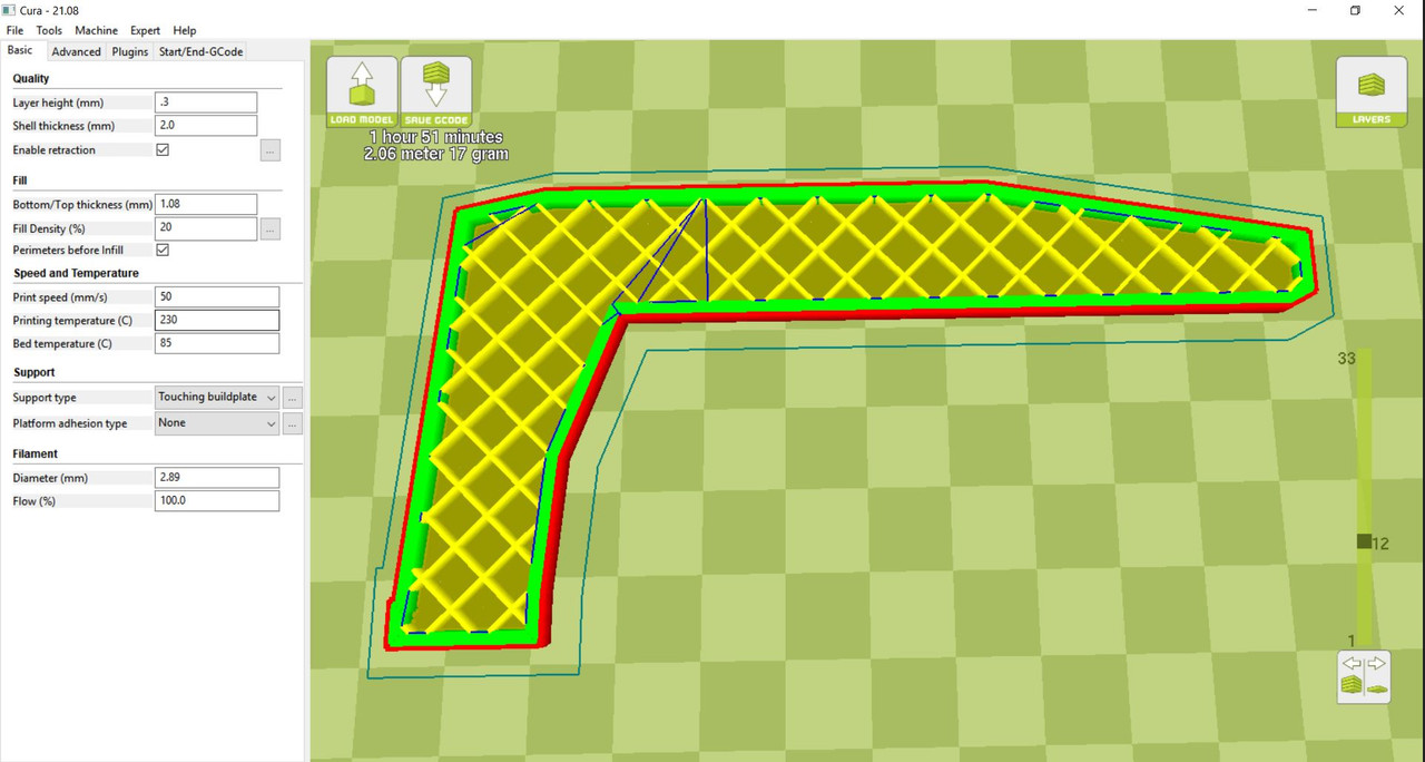
Sample C: This was set up the same as A with the only difference being that the skin thickness was doubled to 2 mm.
[img]
[/img]
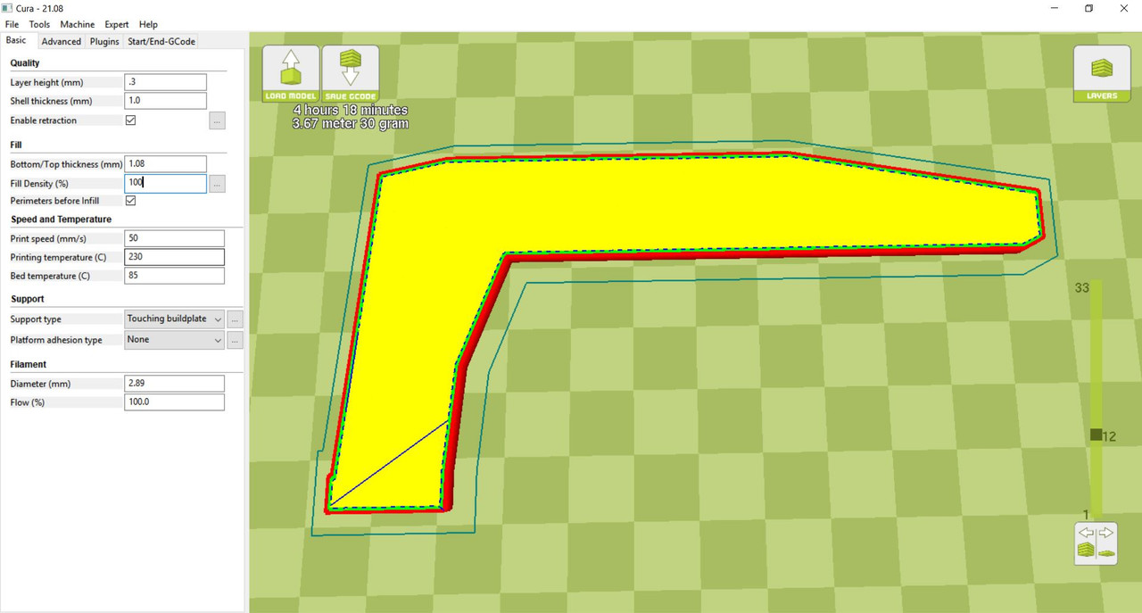
Sample D: This was also pretty much the same as A except that the infill was changed to 100%.
[img]
[/img]
Sample E: For the last test sample I decided to change the shape to see if that would have an affect on the strength. All the other samples were flat sided as was the original. I changed this sample to resemble a gooseneck made from an I-Beam shape. I figured there must be a reason that all the real world lowboys have goosenecks shaped this way. And structural engineering tells us that size for size, an I-Beam shape is stiffer than a slab sided one. Other than the shape, the print was sliced with same configuration as sample A.
[img]
[/img]
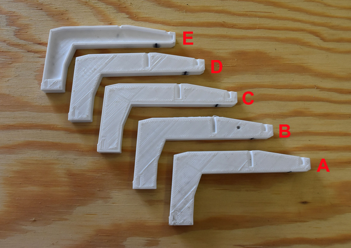
Here is a photo showing all five test samples prior to load testing them.
[img]
[/img]
Some comments about sample B, the one with the metal insert, before continuing with the actual testing. You will note the small hole in the side of B in the picture above that does not appear in any of the other test samples. This is due to an idiosyncrasy of .stl files which are used in 3D printing. Stl stands for Stereo Lithography and was invented quite a long time ago as a means to define a three dimensional object. One of the requirements of creating a .stl of an object is that the object must be “manifold” or “water tight”. In other words the outer most surface of the object cannot have any breaks or openings it it. The software creating the .stl looks at the outer most layer and if it is complete it will create the .stl based on that surface alone and ignores everything else about the object. When I first drew up the part in my 3D CAD program I forgot about this and there was no hole in the side. My CAD program created the .stl of the part and I thought all was good with the world. Till I ran the .stl through my slicer to create the gcode file for the printer. I started to look at the output layer by layer to see where I was going to need to put the “pause” command into the gcode and I couldn't find the pocket! It was gone! That was when I remembered about manifolding. The outside surface was whole so the .stl file converter just ignored the existence of the pocket. To fix this it would be necessary to make the inner surface of the pocket connect to the outer surface of the part. That's what the little hole is for. It goes from the outside to the inside pocket thus connecting those two surfaces into one whole. Sounds confusing but it works. Remember mobieus strips from jr. high math class? Put a half twist into a strip of paper and fasten the ends together. You can now take a pencil and draw a line completely around both sides of the paper without ever lifting the pencil off the paper. Kind of what we have here. I didn't think the little hole would be a factor as far as this load testing experiment went. And that if this were going to be a part to install on an actual model it wouldn't be much of a problem to plug the hole once it was printed.
The other major problem with inserting metal into a print like this. The pocket has to be sized just right or the metal will be too loose or such a tight fit that when you try to insert it you will have to use so much force that you will either knock the print out of alignment or break it. You also have to have the pause command in the exact right place to stop the print so the metal can be inserted and then the print resumed with the tip of the extruder being high enough that it won't hit the metal. My slicer will place the commands to pause the print, move the extruder out of the way and resume the print at the proper location in the gcode automatically once you tell it what layer to pause at. Something else to keep in mind, your slicer will print a skin around the pocket to the same thickness it prints the outer skin. Never having used this function before I had never paid attention to how/when this skin starts printing.
I sized my pocket based on the metal part I had already made. When making 3D prints you learn to make holes slightly oversize to allow for a little squeeze out of the plastic during extrusion. For example if I want a 3mm hole for a screw I usually draw it in CAD at 3.2mm. I did the same when sizing the pocket for the metal insert. But it turned out I didn't make it big enough. The first time I tried to print this part everything worked fine up to the final layer where I had told the program to pause. I Hadn't looked through the gcode first to see exactly where the pause command had been inserted. Over 10,00 lines of code for this part and I really didn't want to search through all of that. Turns out it was placed at the very end of all the print instructions for that layer. So I watched as the printer made the outer shell and then the inner shell and then all the infill. That's when I thought it would pause. But it didn't, It started printing the first layer of the 'skin' that would cover the top of the pocket. Then it paused printing but there was no way I could insert the metal now as the pocket was covered over. If I had tried to cut the skin material out of the way I'm sure I would have probably dislodged the part. Had to abort and start over. Went carefully through the gcode, found where the pause code should have gone before the skin printing code. I decided though that I wanted to make sure the extruder would not hit the metal so went and deleted all the gcode for that first layer of skin over the pocket.
This turned out to be a blessing in disguise. Took the part off the printer, cut away the layer of skin that had been layed down and tried to insert the metal piece. It went in but took a lot of force. Enough force that I don't think that I could have done this during an actual print and not moved everything out of position. Needed to have allowed for more extruder squeeze out than I did. So I used the first print as a template to refine the size/shape of the aluminum part so that it was a nice slip fit. If anyone decides to try this on your printer I would definitely recommend that you first just print the outline of your pocket and use it check the fit our your metal insert. Turned out to be a bit more complicated than I first thought it would be.
(Cont.)