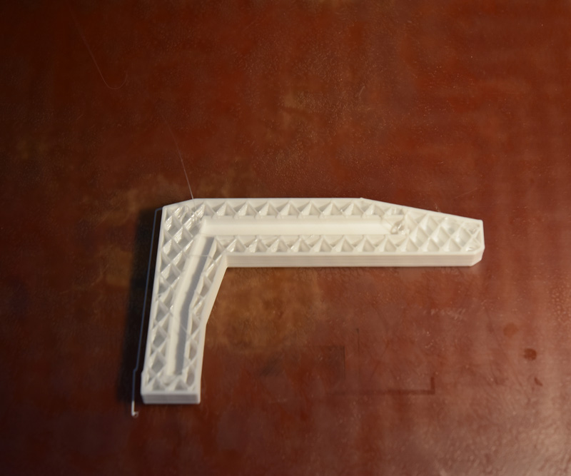
A few pictures of part B being made. Here's the part on the bed of the printer right after the extruder has paused and moved out of the way.
[img]
[/img]
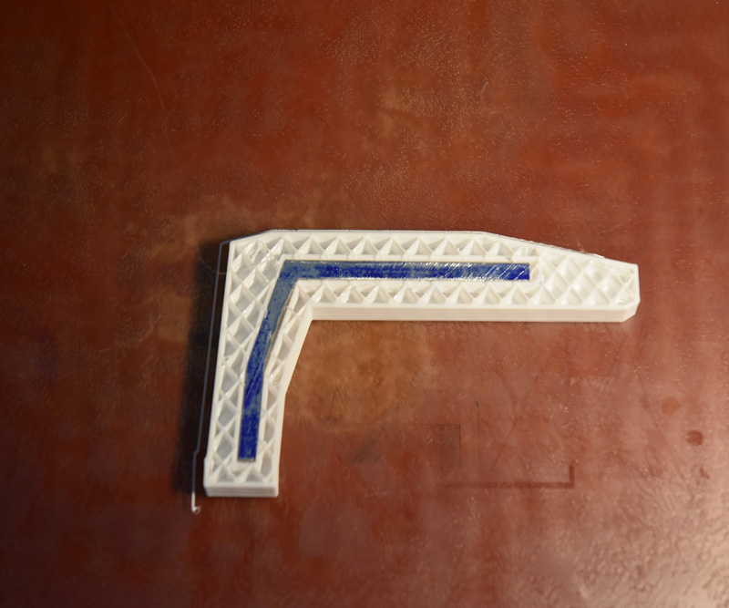
The aluminum insert placed in the pocket.
[img]
[/img]
First layer of skin over the insert.
[img]
[/img]
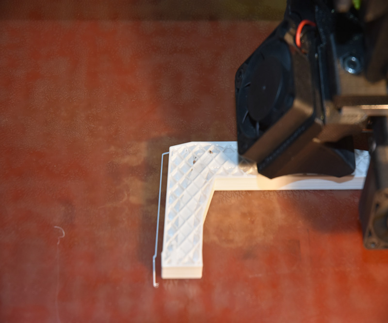
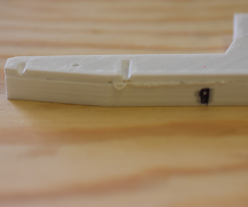
Last internal layer being printed right before the outer skin.
[img]
[/img]
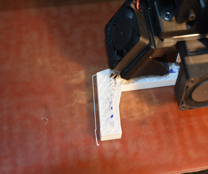
One final issue with this part. When a part is paused during printing, my printer is programmed to move the extruder to wherever you tell it to go. When the print is resumed the print head will automatically first move to the X and Y home switches and then back to where it left off printing. This is supposed to make sure that if the print is accidentally moved the extruder will still start back at the correct location. Was still a little off. Also, even though the pause was for a very short period of time the plastic that was already printed cooled off enough that the next layer didn't bond all that well creating a kind of cold joint.
[img]
[/img]
So it is possible to insert a metal part into a 3D print during the printing process. Is it worth the trouble? Let's find out.
I decided that the easiest way to test these parts was to measure the amount of deflection created by the application of different amounts of weight. I marked the location on each part where the king pin would be located if they were an actual trailer part. This would be where the weight would be applied to each part and help ensure that each was tested the same as possible.
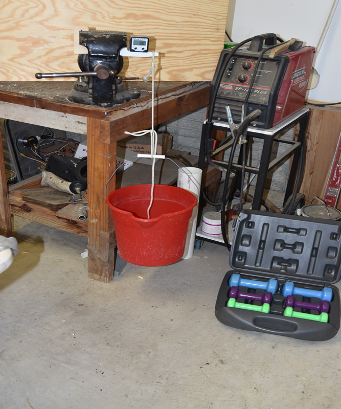
Here is a photo of my basic test setup.
[img]
[/img]
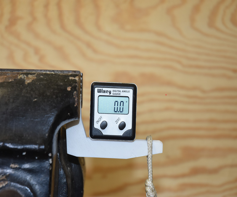
Each test part was clamped upside down in the vise and a bucket suspended from the marked line on each part. This simulates the force on the part as if it were part of an actual trailer. A Wixey Digital Angle Guage was then placed on the arm of each piece.
[img]
[/img]
I used a set of hand weights I had laying around to provide a consistent increase in the amount of weight applied to each sample. Note, this set of weights does not have a 1lb weight. Therefor I could test from 2 to 20 lbs but not do 19lbs. I mention this because when you see the test data there are deflection angles listed for 19 pounds but these are interpolated values based on the results of 18 and 20 lb weight applications. I did this so the data lines in the graph would be continuous.
When I started this testing I wasn't sure that any of the samples would make it to 20 pounds before failing. I was surprised to find that all 5 samples did make it to 20 pounds, but some just barely.
I ran the tests very quickly. I was concerned that if I held a certain amount of weight in place for an extended period of time the plastic parts might keep sagging and this would make it very difficult to compare the results across the different samples. I really just wanted the instantaneous deflection caused by the weights. So just about as fast as I could add a weight, read the gauge and write down the result it was on to the next weight. Only took about a minute to run each set of tests. At the end of each series though I did leave the 20 lb weight attached for up to 5 minutes to see what would happen.
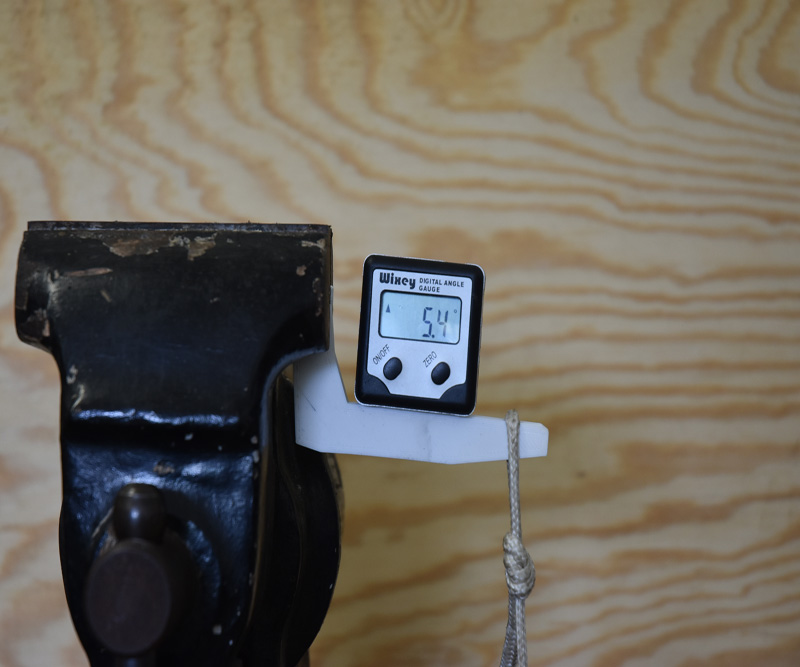
Here is an example of one of the samples being tested.
[img]
[/img]
(Cont)