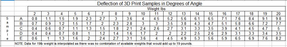
So without further ado, here is a table showing the deflection angles for each weight amount applied to each of the samples.
[img]
[/img]
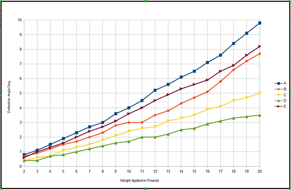
And a graph of the test results.
[img]
[/img]
Basically the way to look at the graph is the higher the line goes the greater the amount of deflection or the worse the performance.
As I expected, Sample A the base line at 20% infill performed the worst. It had the greatest amount of deflection. Interestingly though when I left the 20 lb weight attached this sample just kept bending. It finally got so far down that the rope holding the bucket just slipped off the end. It was amazing to me how far some of these samples could bend without breaking. Even more amazing was that after the weight was released the part sprang back to it's original shape.
[img]
[/img]
Sample B did about 21.5% better. This is the sample with the metal insert. I originally thought that it would do better than this and was a bit disappointed. After having some time to think about it though I think there are some additional questions that need to be answered about this method. Should the metal insert have been bigger? Steel instead of aluminum. Different position within printed part? How much of the increase in strength was actually from the extra plastic around the pocket? When I mounted this part in the vise it started to split in the joint created where the print paused. Because of this I wasn't able to tighten the vise as much as on the other samples. It did hold up through the application of the 20lb weight but might have done better if it hadn't started to split. It continued to sag more with the 20lb weight kept attached but after about one minute it pulled free of the vise. Truthfully I don't think I will try this again. Took a lot of work and I got much better results with other methods.
Sample C, the double thick skin print, did 50% better than A. Doubling the wall thickness really stiffened the print up. This was pretty impressive and would be a good way to stiffen load bearing parts for other models. You would see a slight increase in print time and plastic used but not any where near the increases you see with just upping the amount of infill. For these samples CURA estimated the print times at 1hr 41min for A, 1hr 51min for C and a full 4hr 18min for D the 100% infill print. Like the previous samples, when I hit the 20lb limit of my test I let that weight hang on the part for five minutes. During that time it only sagged an additional 0.5 degrees and then quit moving. When the weight was removed it sprang right back to it's original shape.
Sample D, the 100% infill part, did the best of all my samples. It's deflection under 20lbs of load was 64.3% better than the baseline version A. The downside is that it also took about 3 times as much plastic to make and about 3 times as long to print as sample A. Again, after the 20lb test was reached the weight was allowed to hang on the part for an additional 5 minutes. At the end of that time it had only sagged an additional 0.2 degrees and, again, returned to it's original size and shape. If you can afford the time, this appears to be the best way to go as far as strength is concerned.
Sample E, the I-Beam shaped part, turned out to be a disappointment. I was hoping for much better results. It was better than the baseline set by A but only by 16.3 percent. During the 20lb for 5min duration test it failed. The deflection angle started to increase rapidly and after about 50 to 55 seconds it suddenly snapped off at the vise. This was the only complete failure.
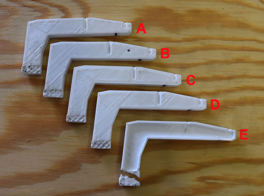
Here's a photo of all the samples after their testing.
[img]
[/img]
So all in all, an interesting experience. Got to try out some ideas I was wondering about and learned some things. There is still a lot of experimenting that can be done. I don't think I will be doing any more though for awhile, too many other irons in the fire. I think, based on these experiments, that if I ever build another one of these lowboy trailers I will design a gooseneck that is a combination of D and E, the I-beam look with the 100 percent infill. I really like the look of the I-beam style and shouldn't take near as long to print as a solid beam would.
Hope you find this informative and of some assistance if you do 3D printing. If you do any testing like this please share your results.
END