Bruder Piggyback Forklift Build part 1
OK, a few caveats first. Like any of these Bruder conversions there are a number of ways to do it. This is the way I did it with the parts I had, and I'm sure there are other/better ways. Experiment and have fun. Post up your builds if you do something different.
Second, I will not build one for you and I will not provide parts. As stated in my first posting I used the Thingiverse parts as the base for my build. And while I ended up only using a few of those parts the others that I made were based on them. And while I am fortunate in having a fairly well equipped shop to work in I think all the parts could be made with hand tools and/or a simple 3D printer.
Lastly be aware of the limitations of this model. This is a lightweight toy. Even with all the RC gear stuffed inside it will tip over very easily, especially if the mast is all the way forward. I just wanted to be able to load my flatbed with pallets holding four scale oil drums. These weigh about 5.3 ounces or 150 grams. My model will handle this but I had to add some lead weight to the rear wheel to do so. The mast and forks will also bend to some degree under load. So you are not going to be able to lift the larger loads that other RC forklifts can but it is still a great build.
Lets get to it
The first part, and often the hardest with these conversions, is simply taking the dang thing apart. This forklift is no exception. Bruder intended these toys to hold together through all the beating a child could give them.
(EDIT: moved this paragraph here from part 2 because if you don't do this first you can't take the model apart)
The first step, if you haven't already done so is to remove the rear drive wheel from the model. This is easily accomplished by simply cutting the top knob of the steering control off right where it meets the upper body.
[img]

[/img]
The drive wheel and support mount should fall right out the bottom. Carefully pull the wheel/tire off its axle and set it aside. The rest of the mounting will not be used and can be discarded.
I used several small and thin screwdrivers and picks to pry locking tabs back and try to pull a joint open. I started at the front of one arm and just worked my way around using toothpicks to shove into open joints to keep them open. Go slow and easy and it will come apart. One good thing about this model I found is that the wheels will pull off their axles fairly easy without being damaged.
[img]

[/img]
I figured that I was probably going to have to put this thing together and take it apart a lot of times before getting done and I didn't want to go through that disassembly headache every time. Plus making it easier to do maintenance/repairs in the future. So first thing I did was to take every locking tab;
[img]

[/img]
and sand them flat.
[img]

[/img]
Then to hold the model together I drilled a hole through both top and bottom pieces at every location where there was a locking tab and installed a #2 sheet metal screw.
[img]

[/img]
DO NOT drill/screw the two locations in the front center as I have here. I didn't think of it at the time, but once the mast assembly is put back in place you can't get to these. Don't need them, the other six screws are plenty.
Prying the tabs from underneath I then removed the ROPs and driver seat.
[img]

[/img]
Now is probably a good time to go ahead and start cutting away a lot of the internal plastic that has to be removed to make room for all the RC parts. Keep in mind that I removed plastic at different times during my build as I was working on trying to fit a specific component. You will see in future photos this progression of removal. But you can go ahead and remove almost all of it now. The body remains quite stiff and strong so there is no real risk of breaking it without all it's internal bracing.
[img]
 [/img]
On the bottom half you can remove all the parts with the green outline. A Dremel or similar tool is the easiest way to do this. Just cut/grind away everything until you reach a flat surface. Go slow and easy to avoid the tool kicking away and damaging something you don't want cut. The area outline in yellow you may want to hold off on for the time being. I had to lower this area to clear the servo arm I used to move the mast assembly in and out. Depending on your servo/mount combination you may not need to. Finally the two parts outlined in white. Be careful not to cut/grind/damage them in any way as these are the rails the mast assembly slides on.
[img]

[/img]
On the top half of the model cut/grind away all the areas outlined in green down to flat surfaces they are attached to. Again, you may want to hold off on cutting away the cross shaped part outlined in yellow. The end of this part is a guide that keeps the mast assembly from tilting forward under load. Unfortunately this area is also about the only place you can fit a battery pack. I ended up having to remove this part and found it's loss to not be a problem. Comparing my finished model to the the original I found that the amount of up/down movement in the mast assembly is about the same.
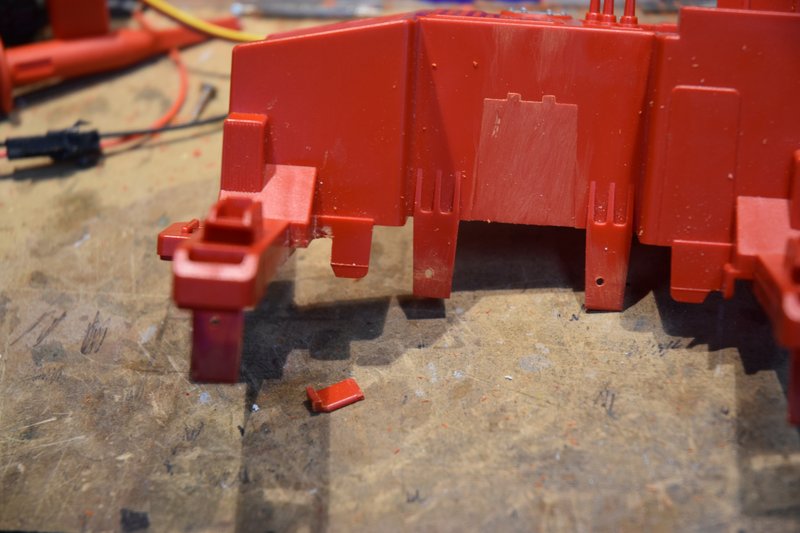
Moving to the outside of the model, cut off and sand smooth the mast grabs at the front.
[img]

[/img]
Need to clip away a bit where the right arm extends from the body to clear the area where the mast extend/retract rod will have to be. You may want to wait on this till you have your servo and control rod in place so you can see exactly where and how much to remove.
[img]
[/img]
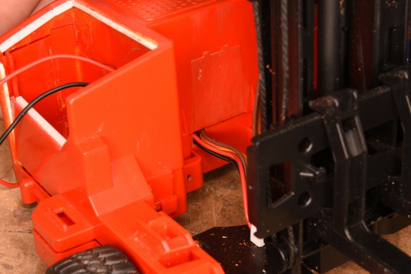
I had to cut an opening as shown for the wiring from the mast lift motor and tilt servo to enter the body. Again you will probably want to wait until you know exactly where and how big to fit your build depending on your components.
[img]
[/img]
Lastly, for this posting, I like to install a master switch to control all the power on my models. I typically use a miniature 6A rocker switch. I thought that a good place for it would be under the operators seat and so cut the appropriate sized hole.
[img]

[/img]
That's all for this time. Have fun.