Bruder Piggyback Forklift Build part 5
I'll start this posting off by installing the lead screw. In the previous post there was a photo showing 5 of the parts that can be used for this conversion from Thingiverse. The originator of these parts did not incorporate any way to secure the lead screw to the mounting piece that goes on top of the upper mast assembly. Looking at the photos of his build he posted on Facebook he simply just glued the lead screw to the top of the mount with a blob of some kind of adhesive. This is the one thing about his build that I really did not like. I decided to make my lead screw mount out of 1/4" aluminum bar stock.
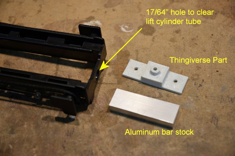
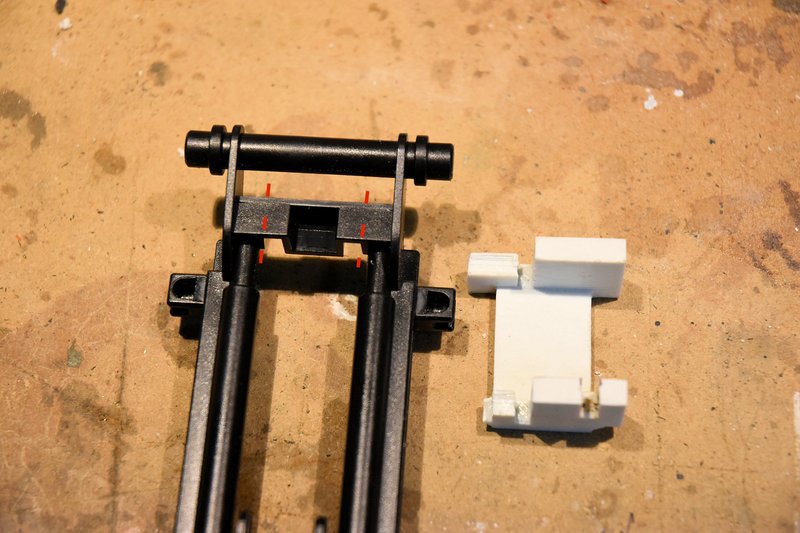
Photo shows the top of the upper mast, the 3D printed part from thingiverse and the aluminum bar stock I used to make my mount. I used my milling machine to make this part but I've made similar parts in the past with a fine tooth hacksaw, files and a little patience. I used the same dimensions as the 3D printed part except I did not add the boss in the top center. What I added was to cross drill through the center hole and tap for two set screws, one from each side. These would hold the lead screw in position and keep it from turning.
[img]
[/img]
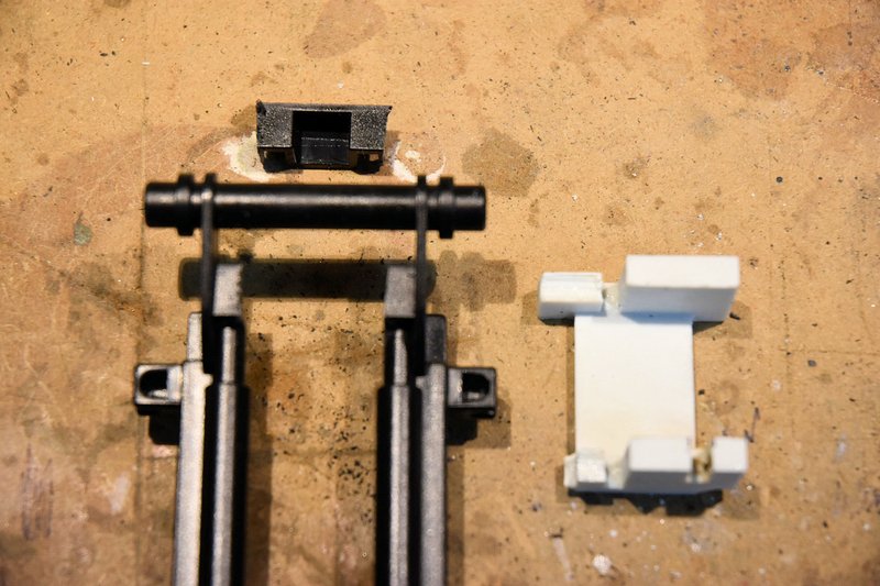
The hole you see in the top of the mast was sized to allow the 1/4" tubing being used for the lift cylinder to extend through to the bottom of the lead screw mount. The hole was located using the 3D printed part as a guide by holding it in position on the top of the mast and sliding a transfer punch through the center hole.
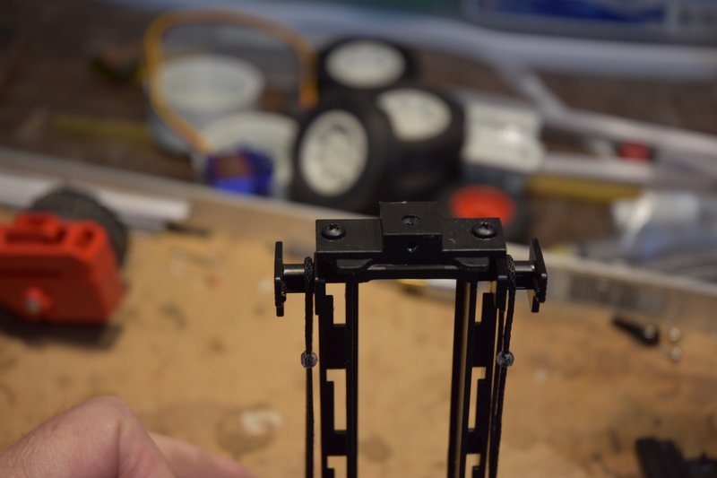
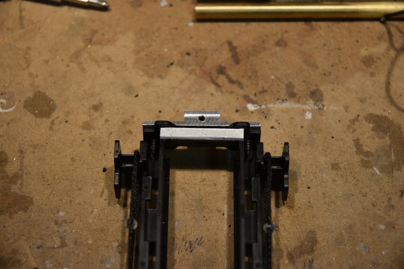
This photo shows the lead screw mount secured in place at the top of the upper mast.
[img]
[/img]
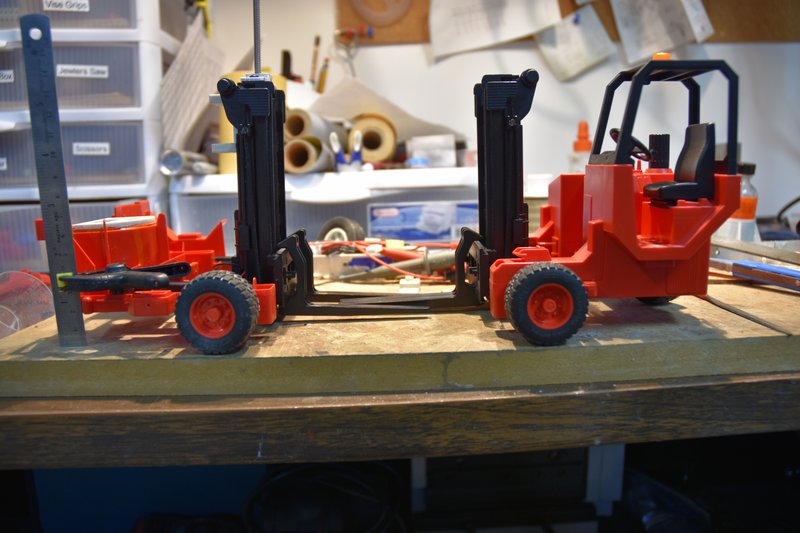
Next is to determine the length of lead screw needed. To do this I put the upper mast back on the lower mast and placed the assembly back on the lower body. I blocked up the rear of the body to match the height of the original toy and set the forks to the same level.
[img]
[/img]
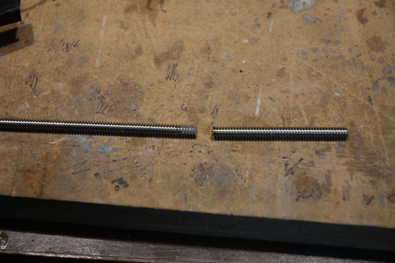
Then I ran the lead screw down through the top of the mount, down though the cylinder until if hit the top of the gear box shaft at the bottom of the cylinder. Unscrewed back about 1/2 turn and marked the lead screw at the top of the mount. This is where the excess screw needed to be cut off.
[img]
[/img]
After cutting the excess off I filed two flats on the end of the screw for the set screws in the top mount to bear against and keep the lead screw from turning.
BTW: one big benefit of having my parts assembled with screws as opposed to gluing them, it is relatively easy to remove the lift motor, cylinder and lead screw to check fits and make adjustments. I bet I had these parts in and out a couple of dozen times during the conversion.
Next comes the real fun, the limit switches.
The fourth photo of my last post shows some of the parts in the Thingiverse files. We need the part in the lower right called 'ups_tipper'. This part actually serves two purposes. The back side will hold the servo for tipping the mast forward and backwards. The front side serves as the mounting plate for the limit switches. Start by cutting some plastic away at the top of the bottom mast section. The red dashed lines in the photo below show where to cut.
[img]
[/img]
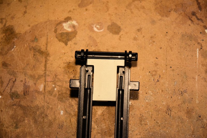
And here is the lower mast with the plastic cut out.
[img]
[/img]
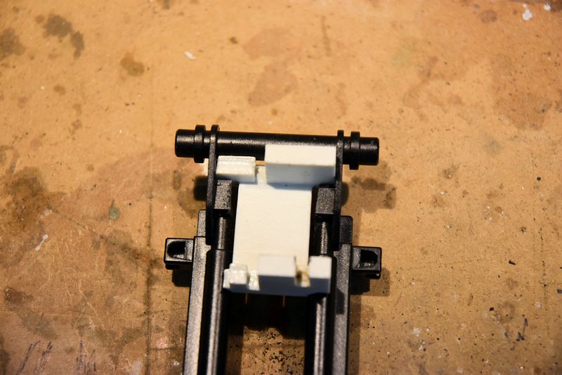
The printed part fits in as shown. The curved portions of the part should fit on the curved sections of the mast which I guess are supposed to represent hydraulic cylinders.
[img]
[/img]
This is what the front of the lower mast looks like with the printed part in place.
[img]
[/img]
Fortunately for me I did not glue this part in place. I thought it might be a good idea to check the fit of the switches I was going to use and make sure they would fit between the mounting plate and the lift cylinder. They did not!!! I was using the same size/type switches that the originator of the parts files used. These are 2A mini snap switches and are about 5.8mm thick. After some head scratching the cause of the problem was obvious. The printed cylinder is much smaller in diameter than the 1/4" brass tubing I used to make my cylinder. If you use the printed cylinder and other parts and the same type of switch you probably won't have this problem, but check the fit before gluing anything in place.
How to fix. I wasn't going to scrap the brass cylinder. What I decided to do was redesign and print a new mounting plate. After a lot of careful measuring I determined I needed about 2mm more clearance between the mounting plate and the backside of the cylinder. I basically copied the original part but extended the mounting posts by 2mm. I also added a notch to the servo side to clear the servo wires as the micro servo I was going to use had it's cable exiting the body about half way down it's length instead of at the bottom like the mount was designed for.
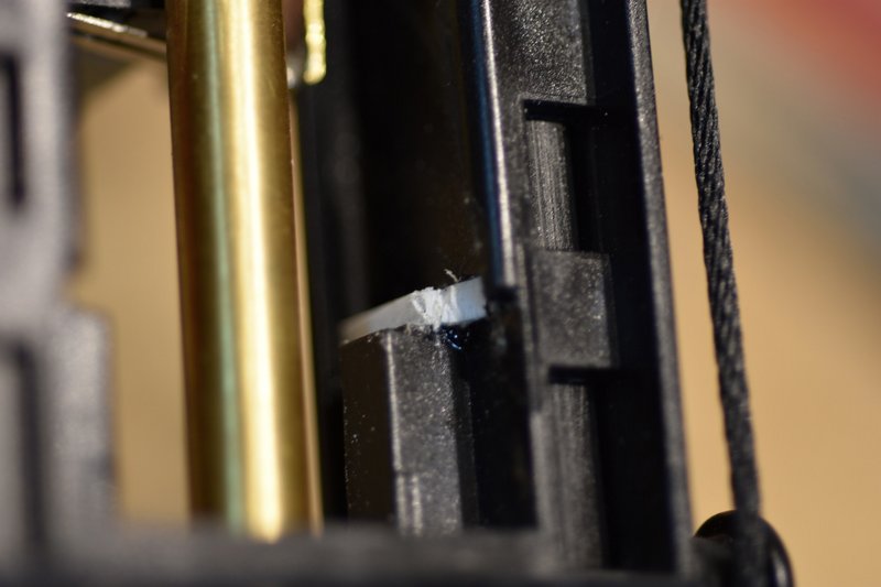
I next found another problem. By moving the switches back 2mm their arms would no longer hit the parts of the upper mast assembly they needed to hit in order to operate. The fix for the top switch (which stops the lift motor as it lowers the mast) was to simply glue on a piece of styrene at the top back of the upper mast extending the contact point back to where it will hit the switch arm. It was left taller than needed and will be filed down to tune the stopping point later.
[img]
[/img]
The fix for the bottom switch (which stops the lift motor as it raises the mast) was a bit more complicated. First I glued in a square piece of styrene that went across the inside of the left upper mast frame. It sits right on top of the part I had to cut plastic from to clear the round head screws I used to mount the lift motor. NOTE: even if you use the 3D printed parts, if you use round head screws for mounting the motor you may have to do this same procedure for the lower switch. I also had to file away some the plastic I added at the front to clear the fork mount.
[img]
[/img]
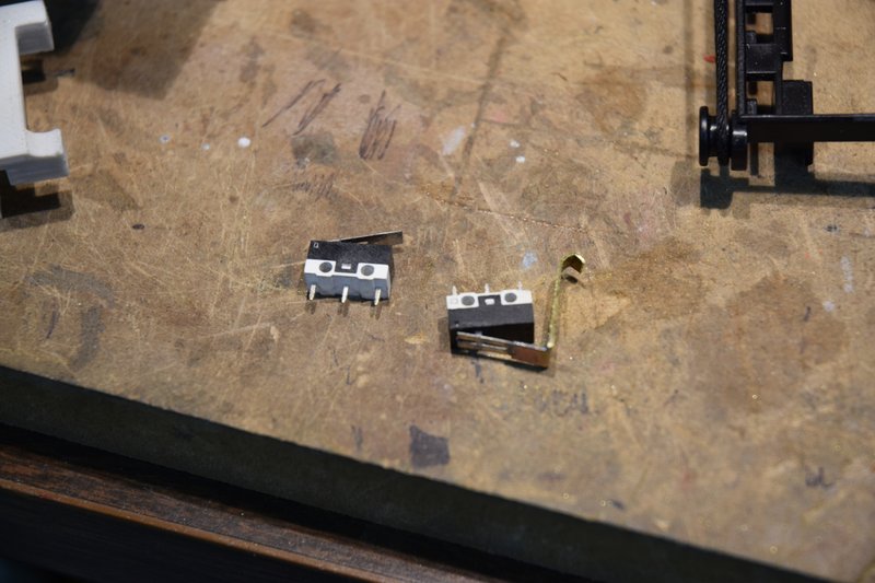
I then had to modify the arm on the switch as it's position would be too low to hit the plastic trip bar I just added. I cut and shaped an extension to solder onto the end of the switch arm. And truthfully I just eyeballed it's length and shape knowing that I would have to reshape and adjust it's position when fine tuning.
Finally, just to make sure the switches would fit I sanded both sides of each switch to make them just a little thinner. Have to be careful that you don't take too much off or the latches that hold the switches together will fail.
This photo shows both switches prior to being installed.
[img]
[/img]