Bruder Piggyback Forklift Build part 5b
(Had to split this post because of posting size limitations)
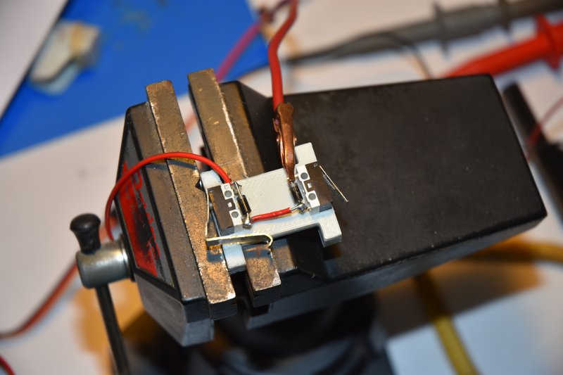
I glued both switches to the mounting plate in positions shown. The switch on the left will be on the bottom when installed in the mast. When cured I soldered diodes and a jumper wire in place. I used 1N4003 diodes which are rated for 1A which is plenty for these little N20 motors. Then tested the switches to make sure the circuit worked properly.
[img]
[/img]
At this point I was now ready to glue the switch mounting plate into position at the top of the lower mast. I used a 2 part epoxy for this. While the epoxy was curing I wired up the lift motor with extra long leads that could be trimmed as needed later. The red wire will go up to the limit switches and the black will go to the motor ESC in the body of the lift.
[img]

[/img]
Next was to run a longer than needed wire into the bottom backside of the lower mast and run it up the right side of the mast to the switches. The lift motor was reinstalled and it's red wire was also run up the right side to the switches. I cut a small notch in the side of the mast even with both switch's lugs and bent one wire over to each switch and soldered into place as shown.
[img]
[/img]
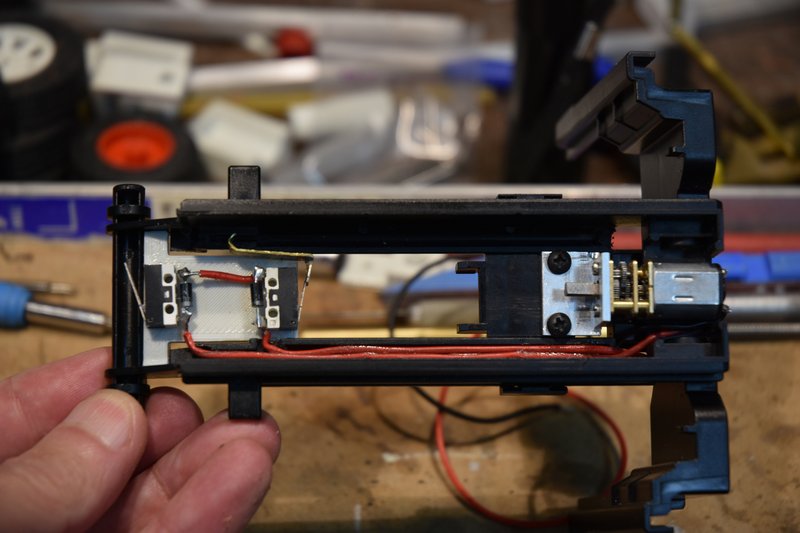
This photo shows the lower mast assembly with the lift motor and completed limit switch mount and wiring in place. Big sigh of relief.
[img]
[/img]
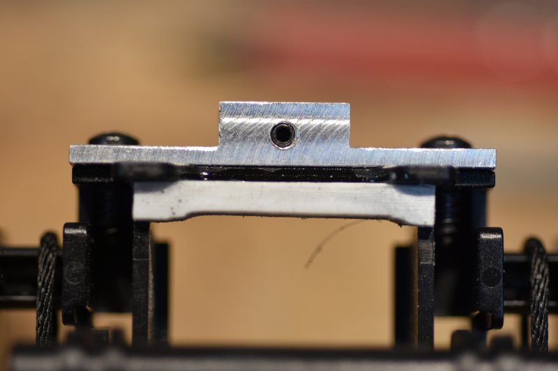
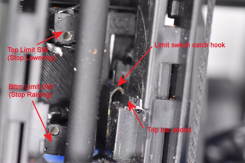
The only thing left was to fine tune the activation of the limit switches. Put the upper mast assembly back into position in the lower mast and installed the lift cylinder. Connected a temporary power supply to the wires from the lift motor and started running the mast up and down. Adjusting the top switch was fairly easy. After lowering the mast till it came to a stop, check the position and if was still a little high just sand a little bit more off the bottom of the trip plate on the top of the upper mast. It ended up looking like this.
[img]
[/img]
Adjusting the action of the lower switch was a bit trickier. I started with the end of the extension I added to the switch arm bent a bit lower than where I knew it needed to be. Raise the upper mast and see where it would stop. Then carefully reach in with a set of needle nose pliers and/or needle file and carefully make a small adjustment to the bend or length of the hook and try again. Took some time but eventually got there. Really big sigh of relief.
[img]
[/img]
I will admit to another error I made. If you look closely at the last photo and the one showing the limit switches mounted at the top of the mast above you might notice that the polarity band on the diodes have changed position. Apparently because I used two red wires up the mast to the switches I didn't pay enough attention to which was which and I got them backwards. The wire to the lower switch was now too short to reach the upper switch so I couldn't just swap them so I had to swap the diodes end for end. Since they were already mounted that meant the swap had to be done with them inside the mast. Not much room for error with a hot soldering iron. Pay attention!
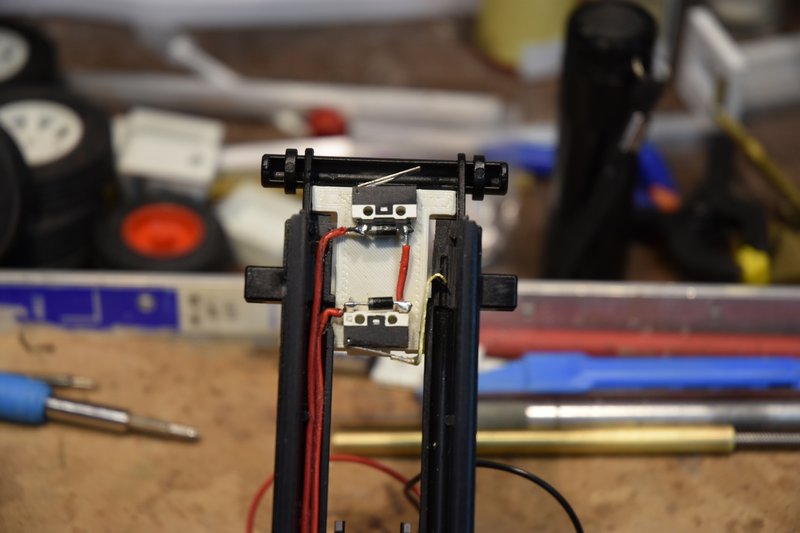
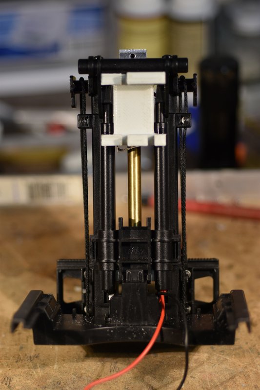
Here is a photo of the completed mast lift assembly from the front;
[img]

[/img]
and the back.
[img]
[/img]
That's all for now. In the next part I'll show how the mast tilt assembly goes together.