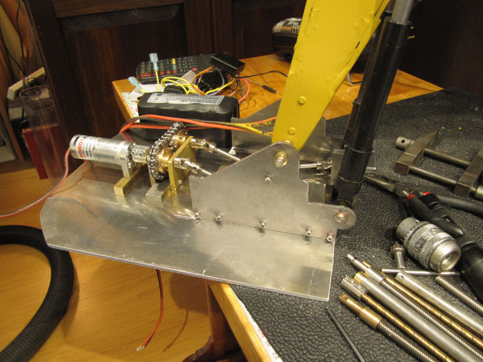
Some more done on the excavator - cut out the outline of the cab floor plate on some aluminum sheet stock, and made up the shafts/holders for the lower boom cylinder drive. While laying things out, realized that I should do the holes for the cab spindle (whatever that is called, the thing the cab spins on over the track assembly) at the same time, save some assembly/disassembly rounds. Here is the floor plate with the parts set on top:
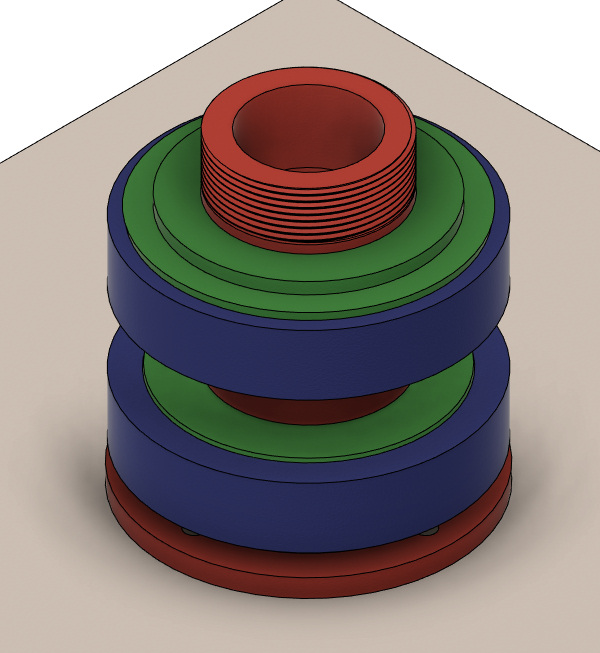
So, back to Fusion 360 to model up the spindle parts. I bought a trailer wheel bearing kit with 1-1/16" center hole size to use, knowing that regular whel bearings are set up to handle all the side/twisting loads. These should be MORE than strong enough for this purpose! Using the measurements of those parts as a starting point, modeled up the assembly. In all these screen grabs, we are looking at the bottom side of things - the square grey background is the bottom of the floor plate, the track assembly will bolt to the flange at the top of the darker grey 'hub'.

Now, to show things better, some more shots with parts peeled away. Here it is with the hub removed, showing the two bearing races/cups inside. The red spindle is hollow to hold the slip ring for the track drive motors. Sides are smooth, end threaded for the spindle nut.
Spindle with bearings removed:

And the hub itself - the step in the center on the inside goes between the bearings, holding the bearing cups apart.

This is all laid out just like the trailer axle/hub would be, just slightly different shapes to bolt to the cab floor and the track frame. Should work, as long as I didn't forget some important part...