Bruder Piggyback Forklift Build part 4
In this post I'll start on the assembly of the mast lift system, specifically the lift motor and screw. The first step will be to disassemble the mast into it's two main components. There is a looped cable on both sides of the mast and you'll note that each has a clear plastic ball crimped to it and held in a square box on both sides. Using a very narrow screwdriver or similar tool stick the blade into the hole on the back side and carefully pry the balls outward.
[img]

[/img]
Then pressing out from the back side the tab shown in the next photo you can pull the upper mast from the lower mast.
[img]

[/img]
And we have the two mast assemblies free to work on. It is not necessary to try and separate the lower mast from the base and I wouldn't advise trying.
[img]

[/img]
This next photo shows some more of the parts from Thingiverse for this conversion with their associated file names. Most of these parts are for the mast assembly.
[img]

[/img]
In my build I did not use any of these parts. I have been building models for decades, long before there were 3D printers. And while I really love my printers I prefer to make some parts out of metal, especially if they will be moving or carrying loads. The thingiverse parts work as attested to by the photos and video the original creator posted on Facebook and If you wish to use them by all means do so. Their assembly will pretty much follow the same procedures I used, you'll just use more glue and fewer screws.
As an example, the motor mount from the thingiverse files to me looked kinda thin. Granted, as discussed earlier, you can't lift much weight without tipping the machine over, but the plastic part is glued to the mast and I've had problems in the past with some glues not sticking well to Bruder plastics.
This photo shows the printed motor mount on the right and the one I made from a piece of 3/4 x 1/2 x 1/16 in angle aluminum. The screw holes were spaced to match the mounting holes on the lift motor gearbox and a couple of ribs on the mast assembly.
[img]

[/img]
I wanted to keep the motor/gearbox as low as possible so that the lift cylinder could be as long as possible. Thus I needed to cut away a portion of the very bottom of the lower mast. The red lines in this photo showed where I cut.
[img]

[/img]
And here is the result:
[img]

[/img]
The holes for the screws used to attach the motor mount to the lower mast were marked and drilled out. I used #2 sheet metal screws. Note the holes are in line with ribs on the mounting surface to give the screws as much material to bite into as possible.
[img]

[/img]
Then a trial fitting of the lift motor.

Note that I used round head screws. This was a mistake. I should have used flat head screws but did not have any at the time and didn't want to go and try to find some. The problem with these round head screws I soon found is that they stick out so far that they interfere with the bottom of the upper mast from being able to slide past. Instead of replacing the screws, what I did was to cut away a bit of the back side of the upper mast until it would clear the screw heads.
[img]

[/img]
This is a picture of the lower backside of the upper mast. The yellow dots represent the screw heads for the motor mount. The red lines are where I had to cut away plastic until the upper mast would slide past the screws. While this solution worked, it led to another problem later on. Should have gotten the flat head screws but too late now.
Speaking of the bottom of the upper mast, some more surgery is required here as well. Need to cut away a portion of the very bottom so it will slide past the motor/gearbox. Looking down from the top rear, this photo shows with the red line what needs to be cut away.
[img]

[/img]
And the upper boom with the piece cut off. This cut also had the benefit of getting rid of the locking tab that prevents the mast sections from being easily pulled apart.
[img]

[/img]
Time for the lift screw. The designer of these thingiverse parts used an M3.5 lead screw for his conversion. It came with a plastic nut that he cut down and glued into the 3D printed cylinder. Note from the earlier photo that the cylinder has larger ends to enable the lead screw nut to be inserted in one end and a set screw to be installed in a cross drilled hole to attach the cylinder to the gearbox shaft. Again, I was a little wary of the strength of the cylinder given it's thinness and wasn't sure how long the set screw would stay secure. I decided to go with a brass cylinder assembly.
I hunted all over the internet for a source of small diameter lead screws in the US. Absolutely no luck. Finally went to Ali Express. I hate that long wait for the slow boat from China. I needed a lead screw with a brass nut so I could solder it to the brass tube I would use to make the cylinder. I could not find a M3.5 screw with a brass nut so I ended up getting an M4 lead screw that came with a brass nut. The screw I ordered was 150mm long which is plenty for this application.
[img]
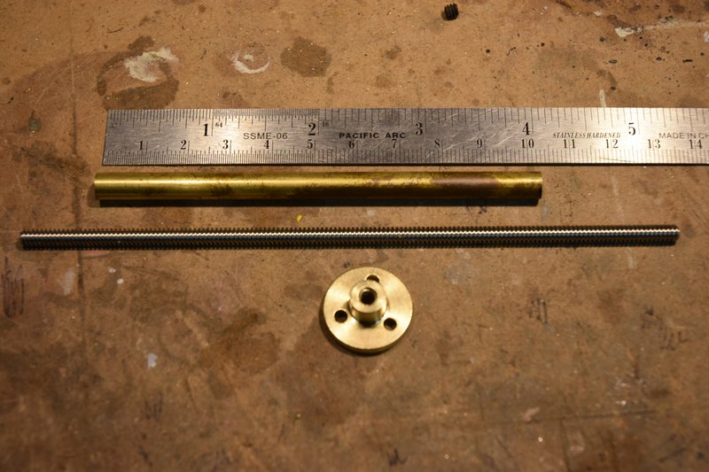
[/img]
Chucked the nut up in a lathe and turned it down to be a slip fit into a 1/4in diameter brass tube. I could have, and found later should have, gone with a smaller diameter tube but I wanted to make sure I could solder the nut in place and keep the solder out of the threads. No tap for these lead screws so would have been a real pain to clean out any solder.
[img]

[/img]
I sized the length of the tube by measuring the distance from just above the gearbox mounting screws to the top of the lower mast. I wanted the cylinder to be as long as possible so that I could get the maximum amount of lift without having the screw come completely out the top of the cylinder. Soldered the turned down nut into one end of the brass tube. In the other end I soldered a 1/4in length of brass rod that was then center drilled 3mm to fit the gearbox shaft and cross drilled and tapped for a #6 set screw. Here is a photo of the screw end of the completed cylinder.
[img]

[/img]
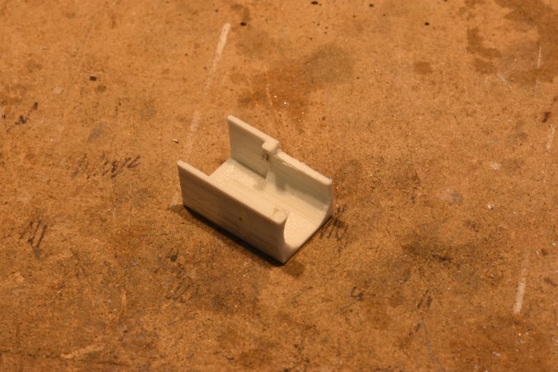
Next I decided to make a cover to hide the gearbox and motor to make for a cleaner look to the front of the machine. So I designed and printed one up. It is just a snap fit over the motor so can be easily be removed if necessary.
[img]
[/img]
Time to check the fit of everything built so far. Attach the motor/gearbox to the front of the lower mast. Attach the lift cylinder to the gearbox shaft. Insert the upper mast onto the lower mast. And, oops, I have a problem. The motor mount is wider that the clearance hole cut in the bottom of the upper mast. No problem. Take everything apart, clamp up the lift motor assembly in a vice and file the sides of the mount down.
[img]

[/img]
Put everything back together (get used to doing this) and check fit. Success. This photo shows mast with upper section raised.
[img]

[/img]
And with the upper mast section fully lowered.
[img]

[/img]
That's all for this post. In the next I'll show what is probably the trickiest part of this entire project. Assembling and adjusting the limit switches.