Bruder Piggyback Forklift Build part 2
I had to wait for a bunch of the parts I needed for this build to arrive so decided to start by making and installing the rear drive and steering assembly. This assembly requires printing out the 'UPS_drive_motor_arm' and 'UPS_steering_mount_V2' parts from the Thingiverse files. In this posting I am just going to cover the installation of the steering mount.
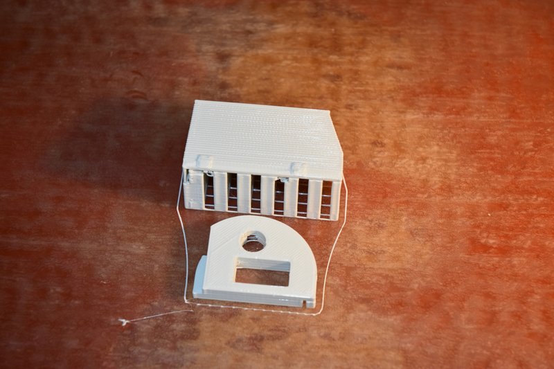
This photo shows the steering mount and battery cover on the 3D printer build plate.
[img]
[/img]
You will note that the steering mount is not symmetrical and the slot for the servo is not centered. How to install this part and keep the servo axis centered in the forklifts wheel well? Here's how I did it.
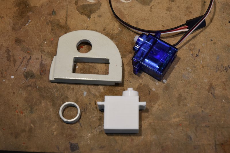
The mount is designed to use a standard 9gr micro servo that is inserted into it's mounting slot from the bottom. You could just install the servo and eyeball the placement but I wanted to ensure that it was dead center. This photo shows the parts I used.
[img]
[/img]
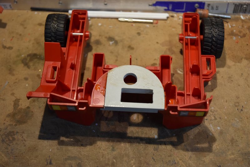
At the top is the steering mount and a micro servo. In the bottom is a 3D printed copy of the servo and a ring. You don't need the servo copy but I already had some left over from another project where they were used to help design the layout of hydraulic components. Using the copy servo kept dangling wires out of the way. The ring was sized to take up the difference in size between the steering mount hole in the back of the lift and the neck of the servo. The ring, servo and steering mount were put together and then placed over the hole in the back of the lift.
[img]
[/img]
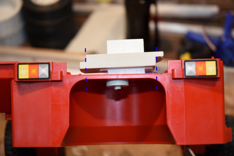
This ensured the axis of the servo was centered in the wheel well. Using a straight edge I then transferred the location of the steering mount sides down to the lift body. I then used a small square to draw out the straight cut lines on the floor of the lift.
[img]
[/img]
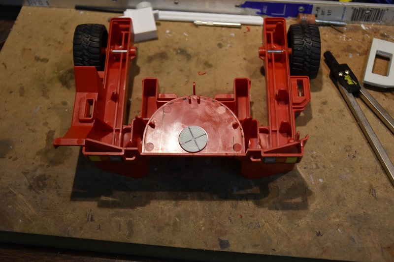
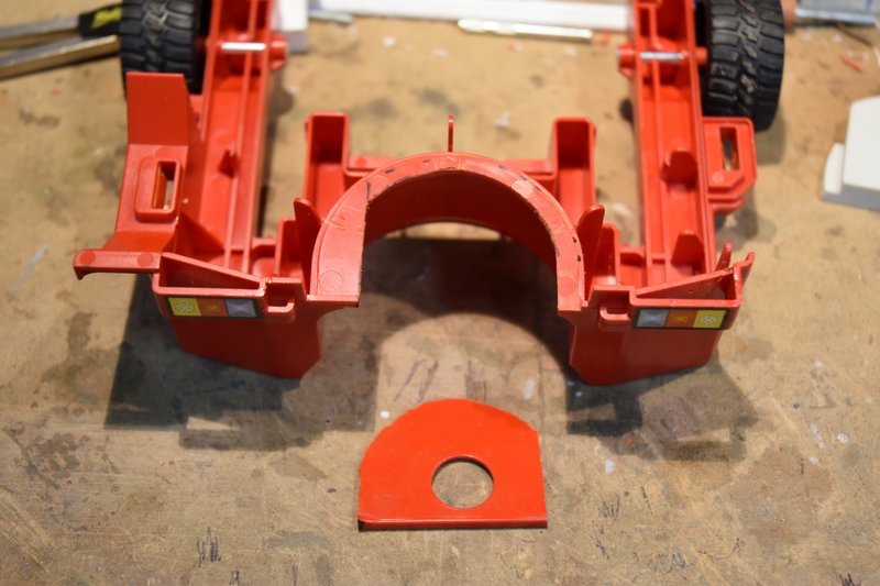
Next I printed a plug sized to fit in the hole of the lift with a center mark drilled in it. This is used to hold one arm of a pair of dividers or a compass set to match the radius of the curved part of the steering mount. The divider or compass can then be used to scribe the curve that needs to be cut out. This next photo shows the resulting guide lines for the cuts that need to be made.
[img]
[/img]
The base is then cut out using whatever method you prefer. I used a short Xacto saw blade on the straight cuts and a length of thread to cut out the curved portion.
[img]
[/img]
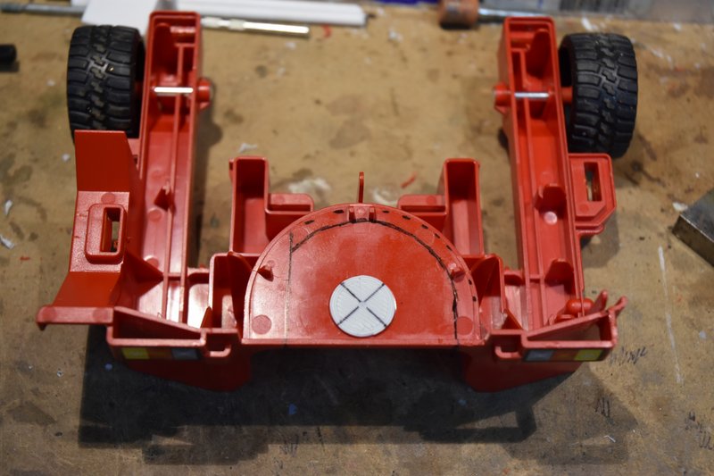
The printed steering mount can now be glued in postion as shown below. I used a two part epoxy.
[img]
[/img]
The reason the curved part of the mount is on top of the floor and the straight part is underneath is because there is a portion of the top half of the lift that hangs down and when installed will almost touch the floor just to the left of the mount. More about this later on.
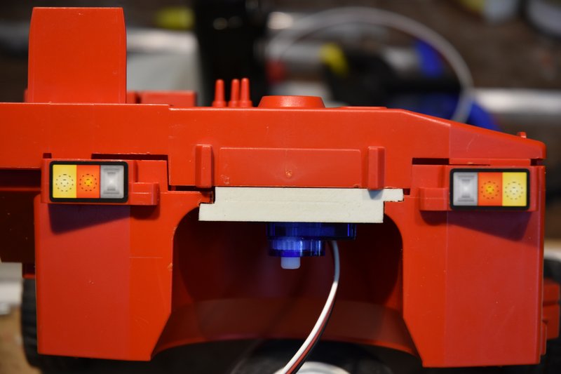
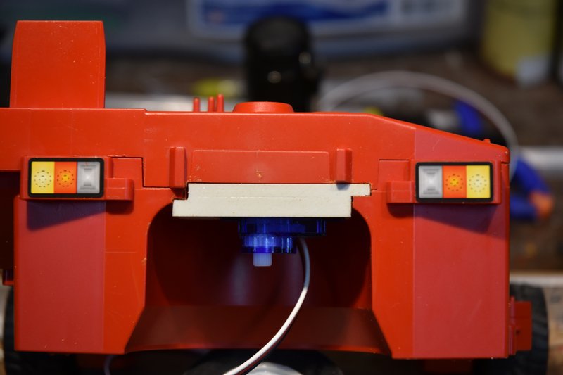
After letting the epoxy cure fully, I installed the servo and then placed the upper half of the model in place to check on fit. As can be seen in the next photo the thickness of the mount is thicker than the floor section removed was and will not allow the two halves to come fully together.
[img]
[/img]
Simple fix, just mark on the upper half where the edges of the mount hit and then cut/file/sand a notch just deep enough that the two halves will come fully together.
[img]
[/img]
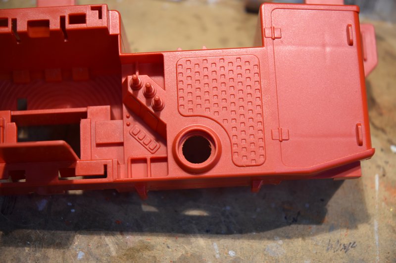
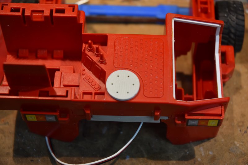
That left a nice big gaping hole in the top of the lift where the manual knob used to be.
[img]
[/img]
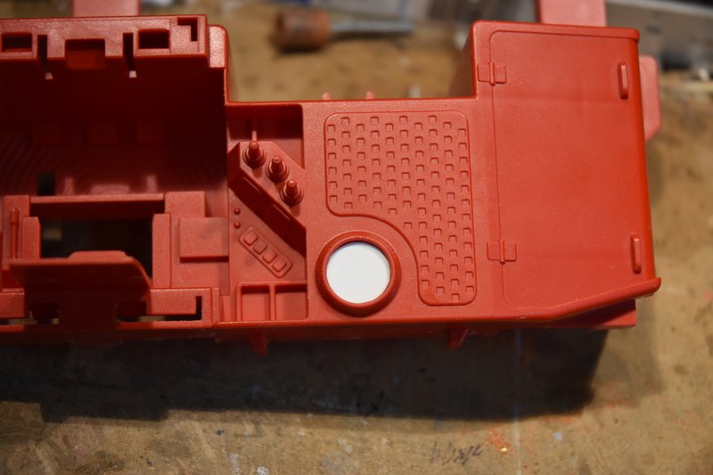
Again, a fairly simple fix. Measure the diameter, transfer to a flat piece of styrene and cut out a disc to glue in place over the hole.
[img]
[/img]
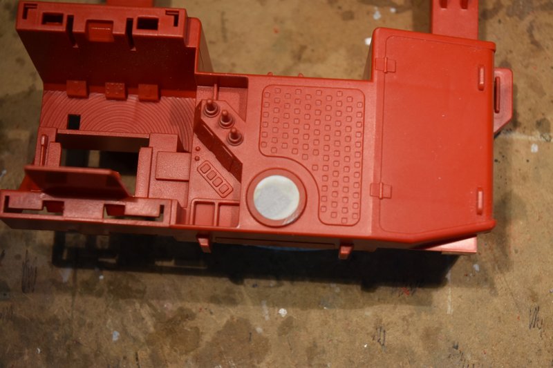
And then file and sand the rim down flush with the disc.
[img]
[/img]
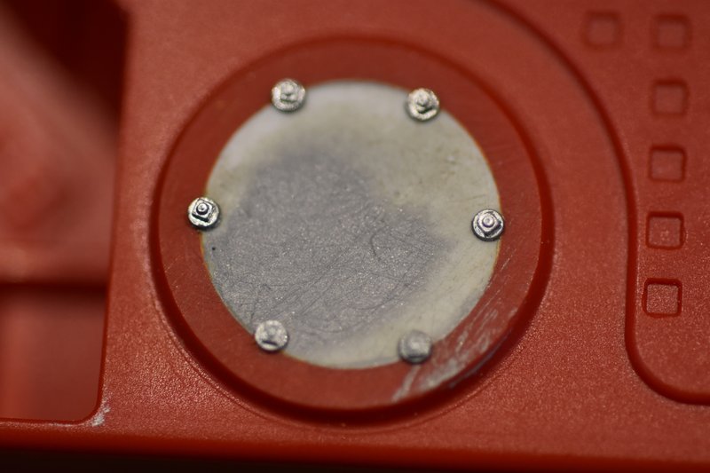
Just having that plain flat disk there kind of bothered me after looking at it for awhile. On a real lift why would it be there? Well maybe we can make it look like an access plate for maintenance. I used to be heavy into model railroading years ago and still have a lot of modeling parts for rail cars left over (never throw anything away, right). Looking through that stash I came across some nut/bolt castings that I thought would dress up that plate and make it look like it could be removed. Measured the outside diameter of the plate rim and printed up a disc with evenly space holes to use a a drilling template.
[img]
[/img]
Drilled holes of the proper diameter to match the castings. Inserted the nut/bolt casting into place and glued from the backside with CA. They are square headed nuts but they are so small that its not really noticeable and I think made a big difference in the appearance of the model.
[img]
[/img]
That's all for this post. I the next one I'll cover the drive motor assembly and installation.