|
|||||||
| Construction Equipment Tech Hydraulics, Electronics, General Engineering, ect in constr equip |
 |
|
|
Thread Tools | Display Modes |
|
|
|
#2
 12-28-2012, 03:19 PM
|
||||
|
||||
|
Hey Jazza check out Trucker47's thread on his loader. Page 4 and Page 5 has photos of his whole hydraulic setup he homemade.
http://www.rctruckandconstruction.co...ead.php?t=3260 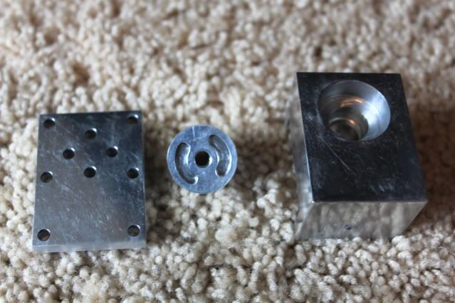

|
|
#4
12-28-2012, 05:11 PM
|
||||
|
||||
|
Valves for our applications are normally fall under the 5/4 port 4 way 3 position setup. As in this picture below trying to explain the ports. Its of a spool valve to get backward and forward control of a hydraulic circuit. I recommend going with the rotary valves shown above. They have the same fluid control but tolerances are easier to obtain than a spool setup. Also I recommend a closed center position so your hydraulics will not creep. How you make each valve is up to you. Individual depending on your application or together on a manifold with pressure and return circuits built in like RCP57's really nice manifold set up.
Ps Pressure from your pump Pr X2 Return circuit. Combined on a rotary valve. Seen on the above pictures. Pa and PbYour lines to both sides of your cylinder. 
|
|
#6
12-31-2012, 12:00 PM
|
||||
|
||||
|
i quite don't get the layout of that pic? i want to make my own vale too. and really having a time with all the hydraulic stuff, price and understanding (pulling hair out)
|
|
#9
12-31-2012, 08:09 PM
|
||||
|
||||
|
Quote:
I spent some more time in cad came up with this. 
|
|
#10
12-14-2016, 01:00 PM
|
|||
|
|||
|
Quote:
|
|
#13
01-01-2013, 01:45 PM
|
||||
|
||||
|
JW : steel or iron next to brass would be the best choice for your manifold . Aluminum does not wear well .
Madda : O-rings work well for the seals as you should only have to seal the shaft of the rotor and the rotor cap . between the rotor and the valve block , you should have a lapped fit .
__________________
RIP FreddyGearDrive 2-12-59/12-19-11 To view links or images in signatures your post count must be 10 or greater. You currently have 0 posts.
|
|
#14
01-01-2013, 03:44 PM
|
||||
|
||||
|
Quote:
|
|
#16
01-01-2013, 04:20 PM
|
||||
|
||||
|
even with the poor tolerances on the Robbie valves , they don't leak . The rotor just chews up the manifold . When I get back to running steel in the mill , I'll be making 2 , 1 for the loader and 1 for the TD40 .
__________________
RIP FreddyGearDrive 2-12-59/12-19-11 To view links or images in signatures your post count must be 10 or greater. You currently have 0 posts.
|
|
#17
01-01-2013, 04:31 PM
|
||||
|
||||
|
so this is all steel? i want to try to make one of these, but i only can cut aluminum on the router table at work. can i use plastic on any parts? and why not aluminum? thanx for the thread guys lot of good info !!
|
|
#18
01-01-2013, 04:45 PM
|
||||
|
||||
|
Quote:
|
|
#19
01-01-2013, 05:58 PM
|
||||
|
||||
|
so what if you put some kind of "buffer" between the Aluminum? like a brass thin shim or washer? of even a brass gasket? the only reason i ask because again i only have the abillaty (<---spelled wrong) to cnc aluminum? the cnc router at work will only route softer metals only because of our bits. and the boss won't let me cut steel on it i asked before for parts for my real car.
|
|
#20
01-01-2013, 06:19 PM
|
||||
|
||||
|
Perhaps some automotive gasket material between the 2 main pieces would work?
Like: http://www.autozone.com/autozone/acc...erial/_/N-25w7
__________________
Brian Finster shavin' and smokin' a cigar?!?!
|
|
| Currently Active Users Viewing This Thread: 1 (0 members and 1 guests) | |
|
|


 Hybrid Mode
