
 |
|
|||||||
| Euro Style Trucks and Trailers A place for the Euro style trucks single and twin axle trucks and trailers... |
 |
|
|
Thread Tools | Display Modes |
|
|
|
#1
|
||||
|
||||
|
Today I bolted on the Rockinger Trailer Coupling. Easy I thought ... only took about 2 hours. (got a bit carried away with pictures here too)
Because there was only €26 (without tax) difference between the manual and the remote controlled one, I decided to go for the radio controlled one. What is in the red square is the manual version, the rest is with the radio controlled one. 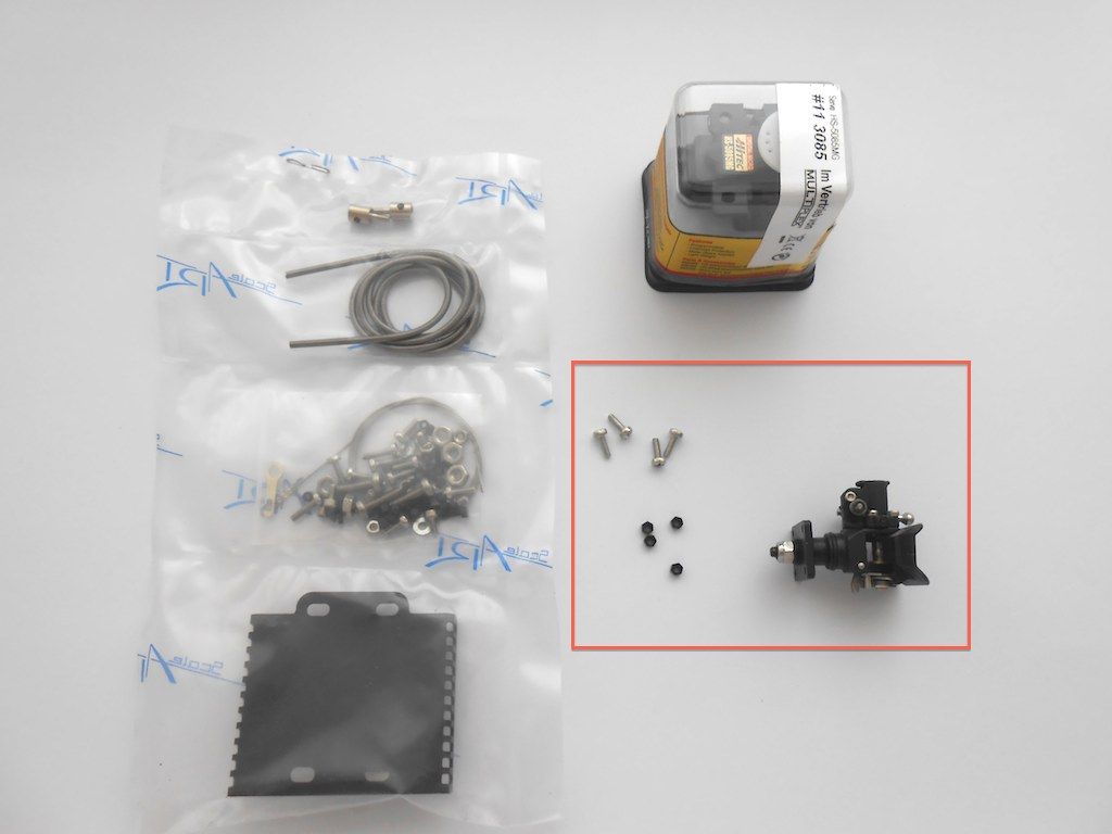 This coupling is truly a masterpiece. Here some pictures Left side 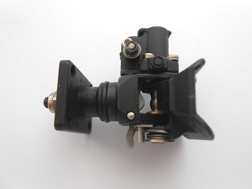 Right side - closed 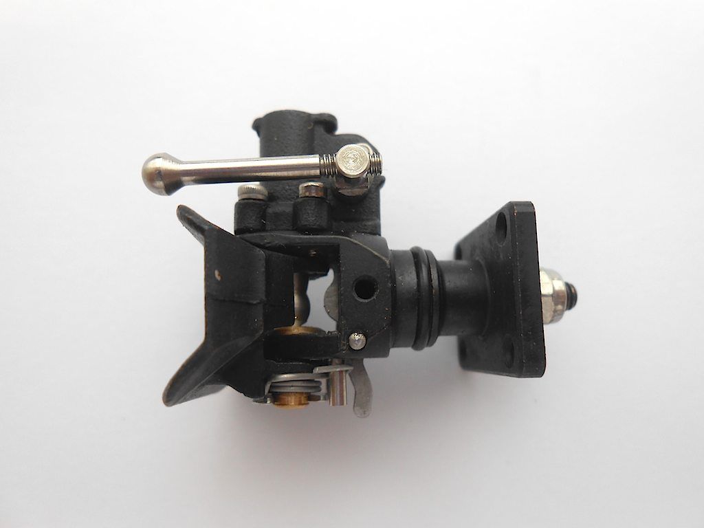 Right side - open (closes automatically when the tongue of the trailer hits the back part - manually with the little lever at the bottom) 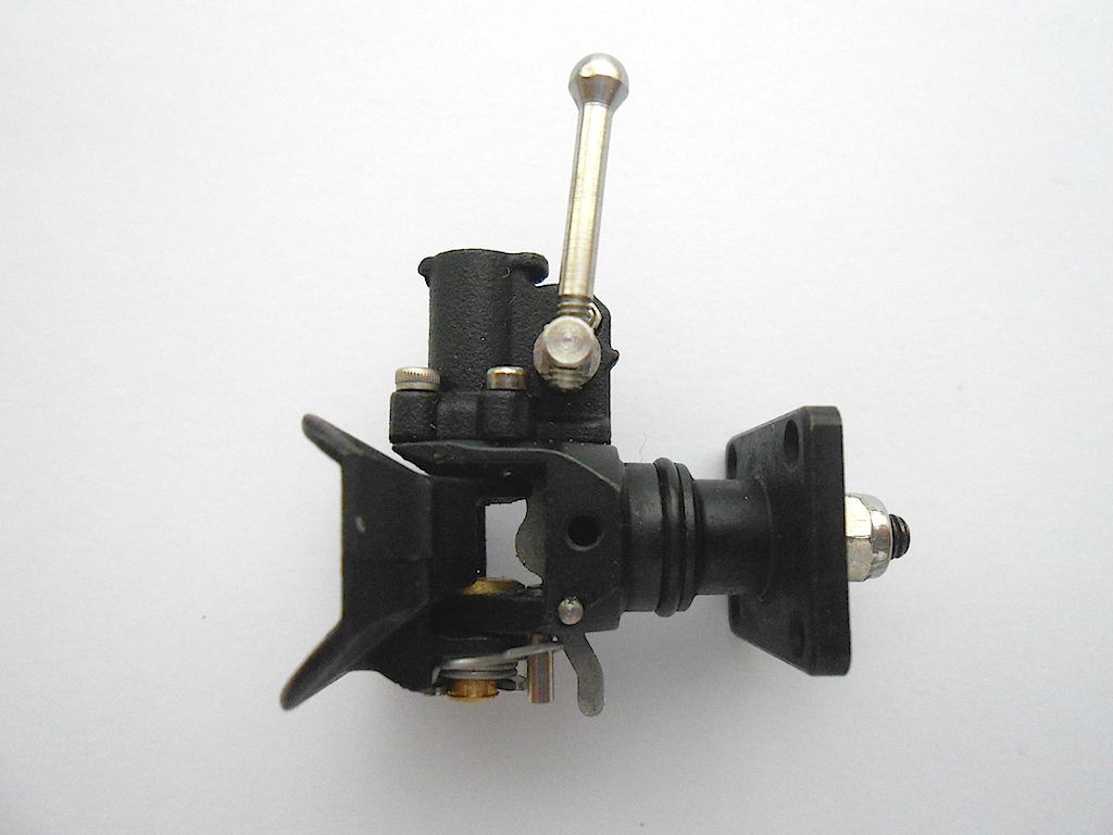 Here a link to a short movie I found on YouTube that shows this: https://www.youtube.com/watch?v=YyJbYVeywP0 Bottom - the spring allows movement to the left and right (no movement when coupling is open) 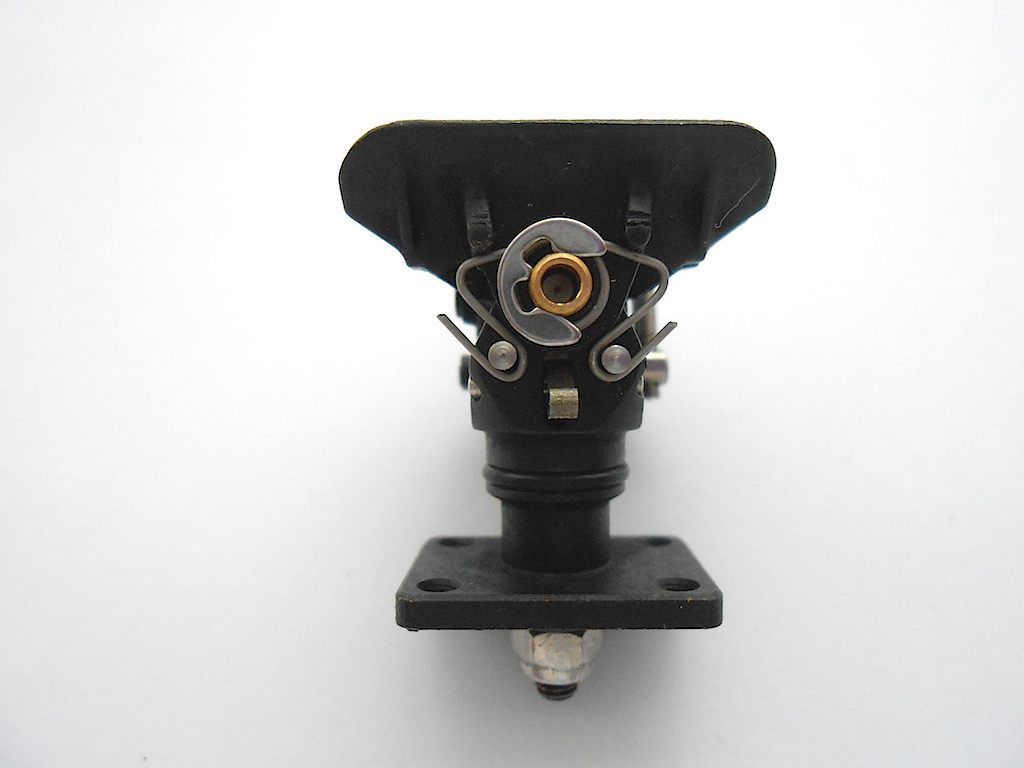 Top 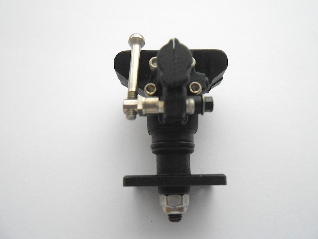 Front 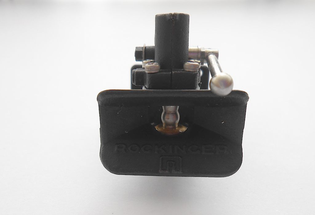 Back 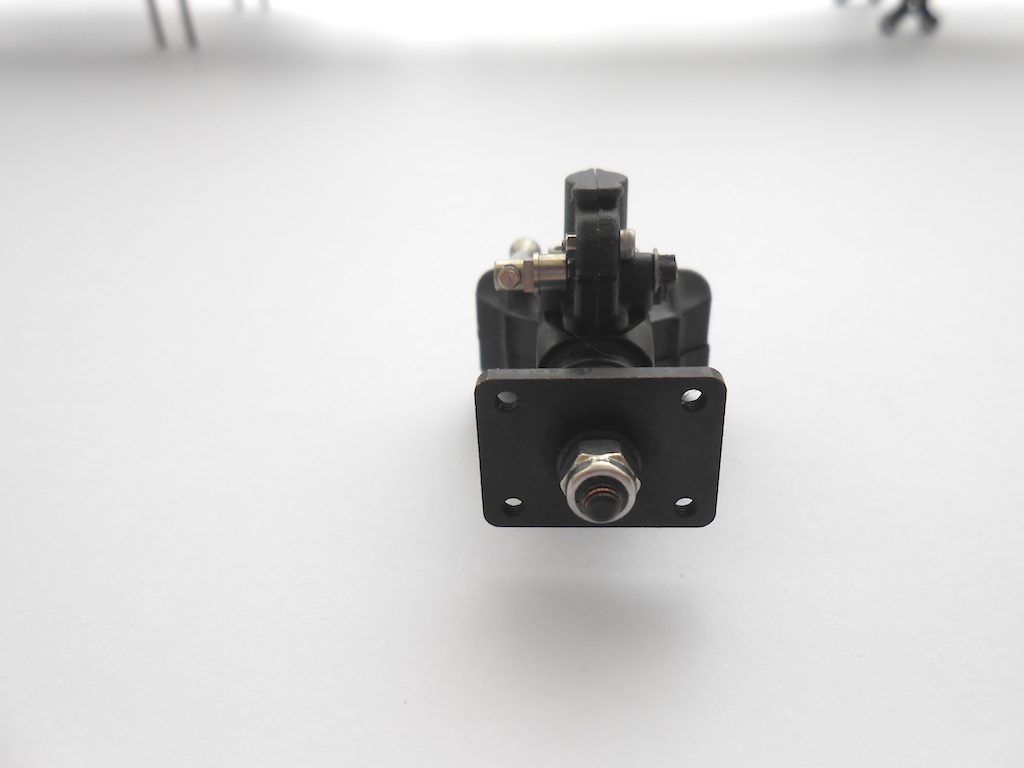 So unpacked the lot and all I really needed was the 2 black bits with the arrow pointing to it, the cable and the servo. The rest are for every possible truck ScaleART produces. So lots of spare screws, washers etc. 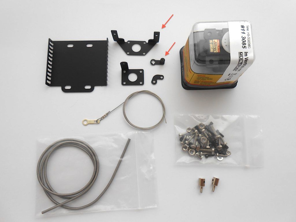 To get the little black lever on, one needs to remove the big stainless one. 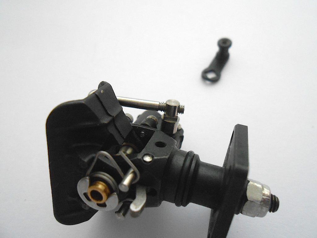 This was not as easy as it sounds, but a bit of scrap rubber to protect the polished metal and pliers took care of it. 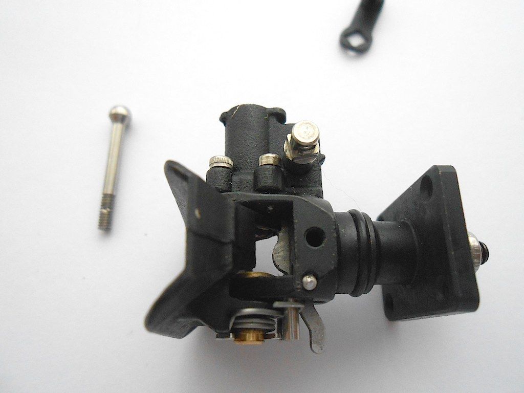 The black lever pressed in place (used a box driver) on the square protrusion. Looks like a grub screw is needed to hold the cable in place. 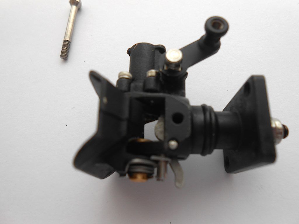 Found in the bag with fasteners. 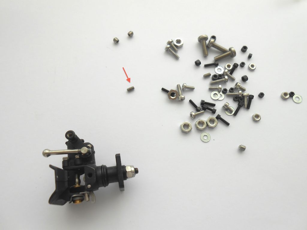 Next the servo support goes in the back cross member of the frame 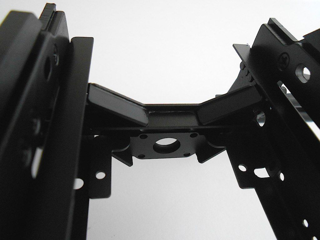 The holes in the trailer coupling have thread in them. Elected not to drill it out. So first screw in the 4 screws. 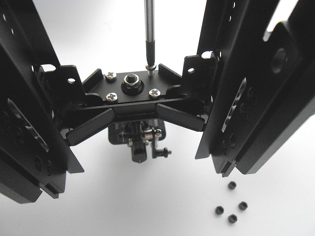 Then loosen each screw in turn and offer up the M2 nut with tweezers (no other way to get to that area) 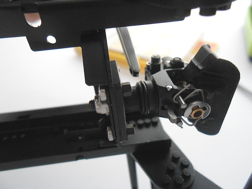 Then screw the screw back in whilst holding the nut with the tweezers, and tighten nut with 3mm spanner. Loctite applied. 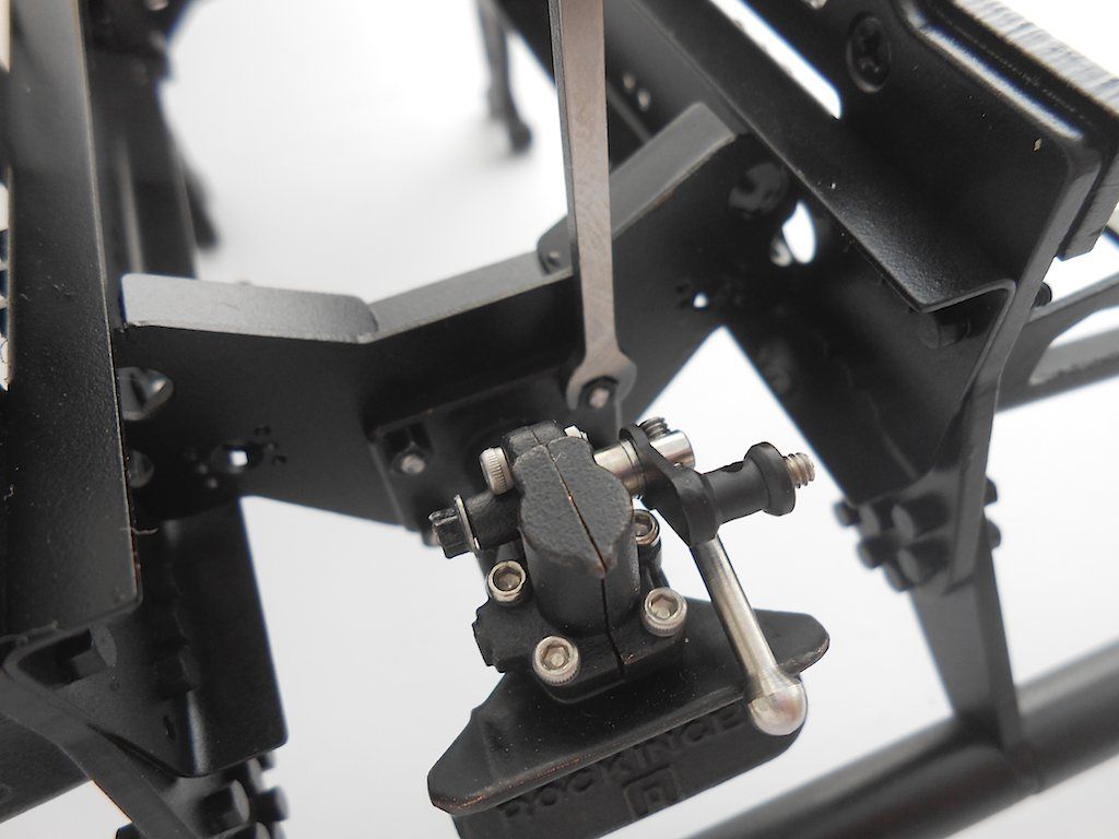 Next up, prepping the servo and servo horn. Temporary attach the cable. I cut the rubber supports in half and filed off a couple of mm of the copper bushings that go in the rubber. I felt that otherwise the servo might sit too high. Can always change this again at a later date. 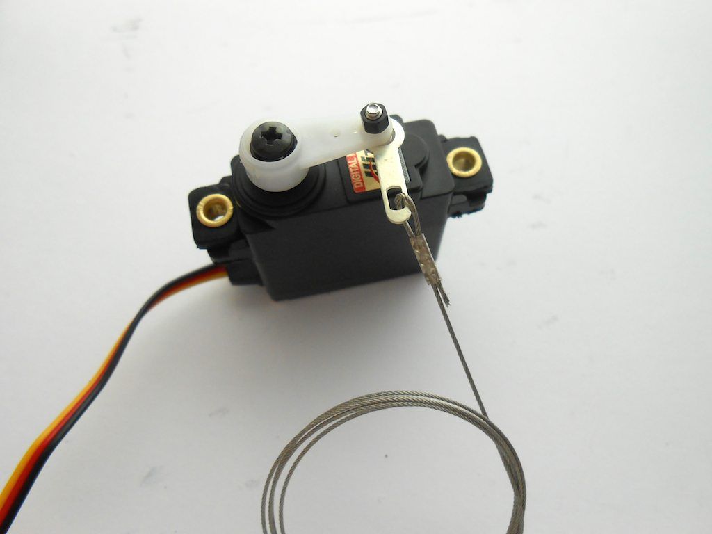 Servo bolted in place and cable trimmed to right size. A blob a glue added to where I cut the cable to prevent fraying. The servo horn is just loosely attached for the moment. I still need to centre the servo. 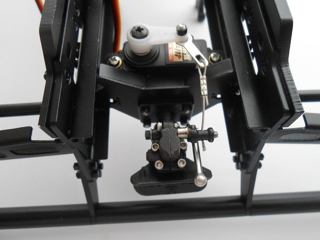 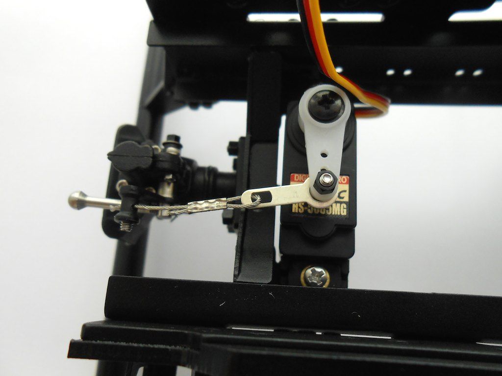 Cheers! Stephan Last edited by Rakthi; 05-21-2015 at 06:00 AM. |
|
#2
|
||||
|
||||
|
Next up is the installation of the hydraulic lift arm.
Here an overview of most of the parts needed for this set - just finding all the bits and pieces was a job in itself  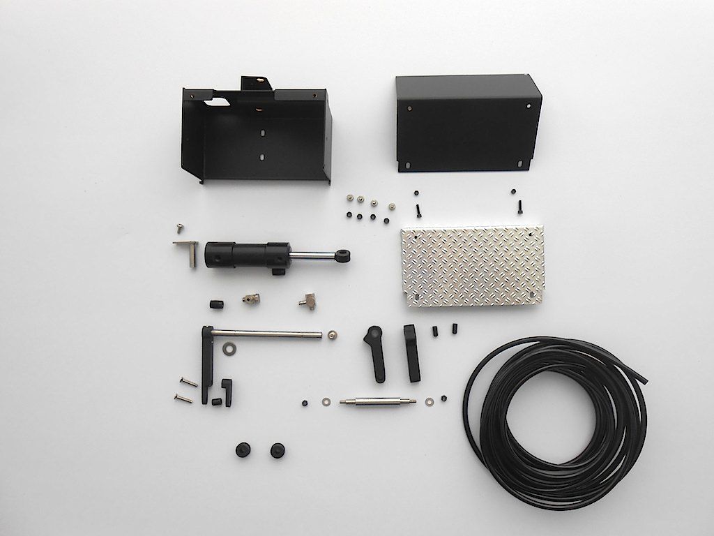 First we prep the hydraulic cylinder 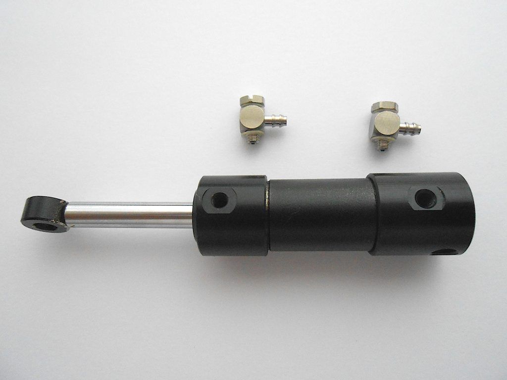 The nipples are screwed on, and although the manual does not ask for it, I added some thread sealant. Better safe than sorry. 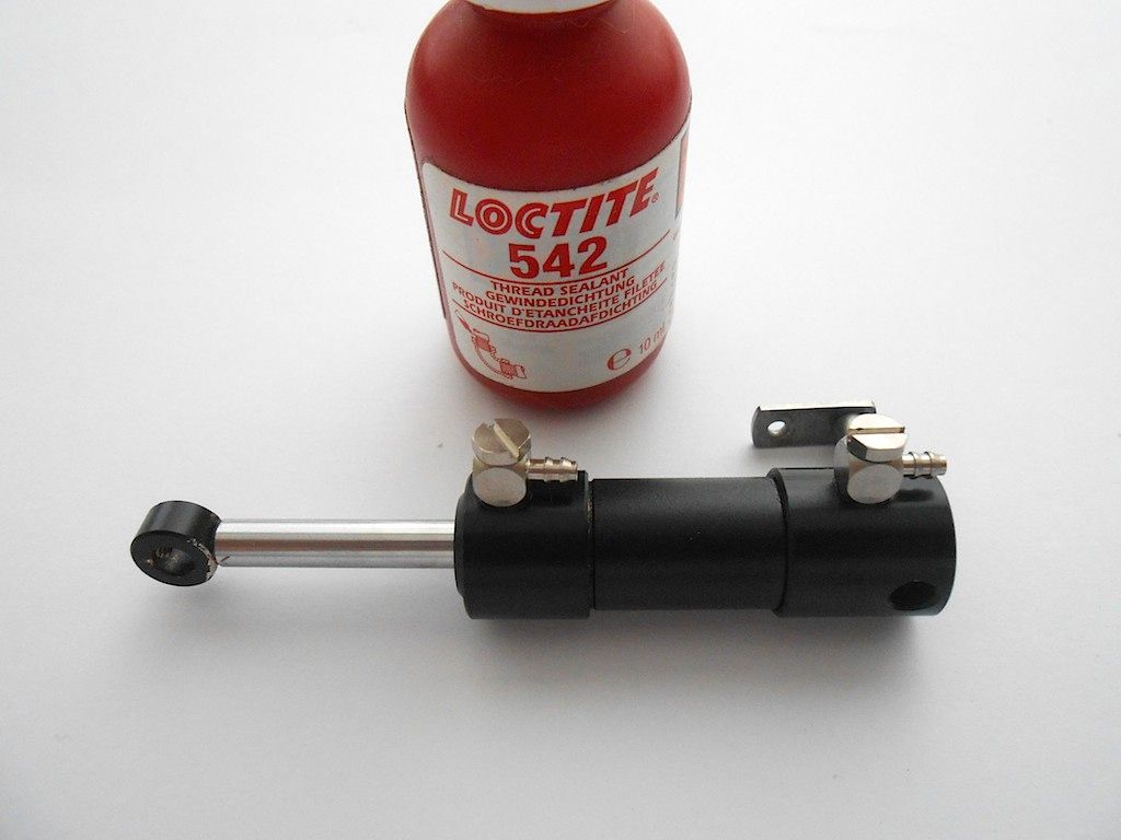 Then temporary mount the cylinder to the hydraulic valve box. Temporary so we can determine the length of the hydraulic hose we need. Would be a real "joy" to have to install this after everything is bolted up. 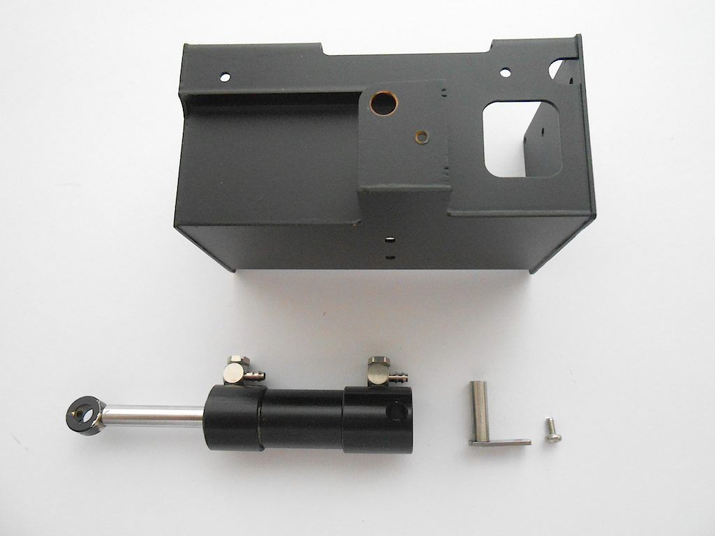 Installed. I put the longer pin in the picture because the short one is the wrong one. 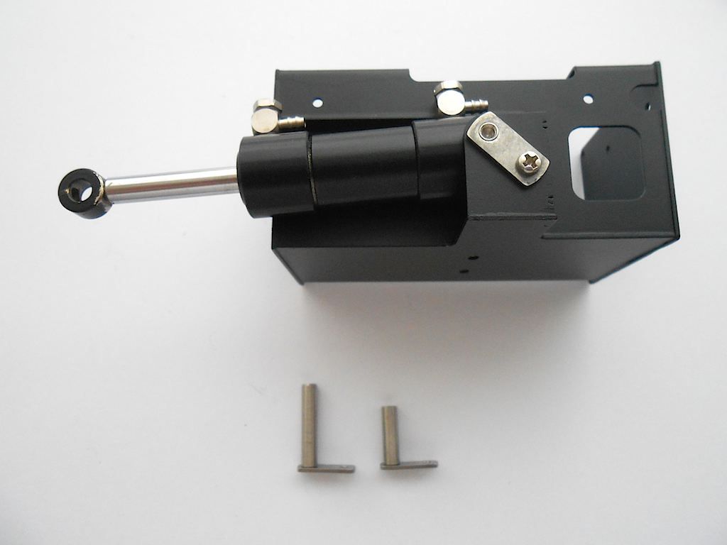 Mounted the valve body in the box to check length hose. 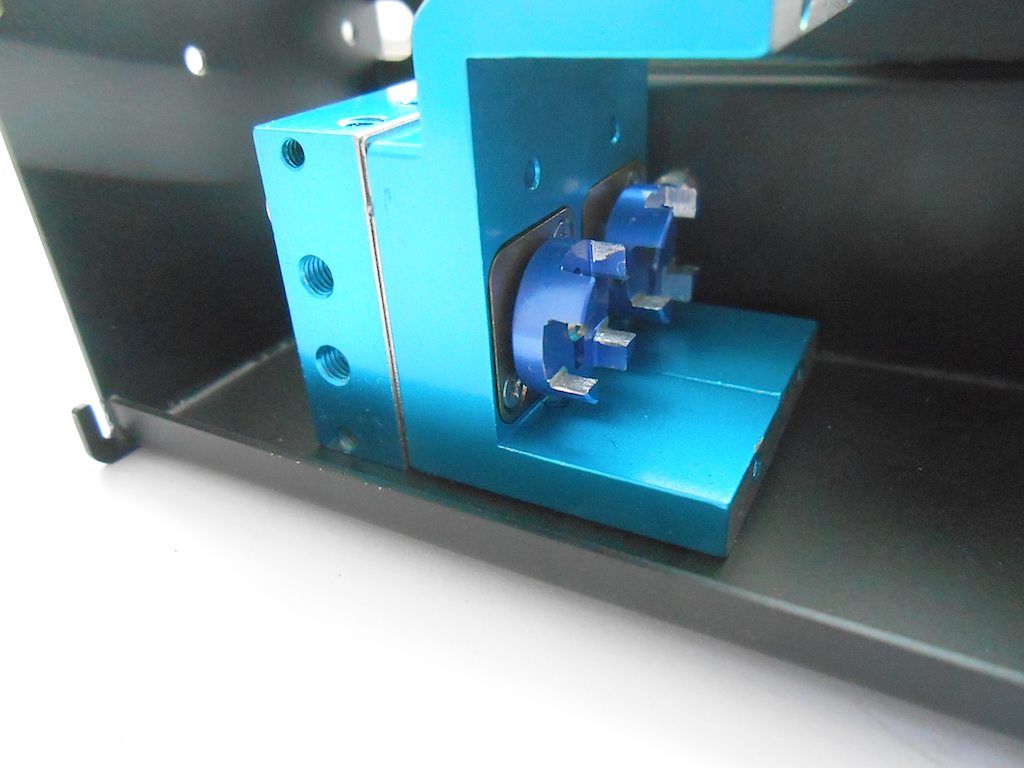 The hoses for this cylinder will attach to the area pointed out with the arrows. The 2 circled holes are the in and return line for the oil. There's been a small error in packing and the 4 mm nipples were omitted. ScaleART already informed me they will ship them ASAP .. still will probably take 4 weeks to get here. 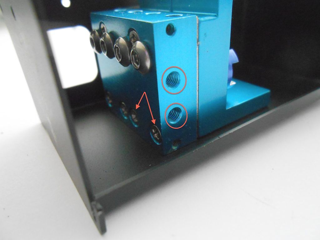 Hose length determined and cut to size, attached it to the nipple. First slide on the hose and then press the sleeve home. 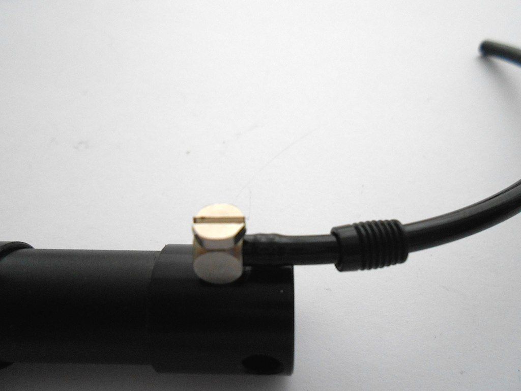 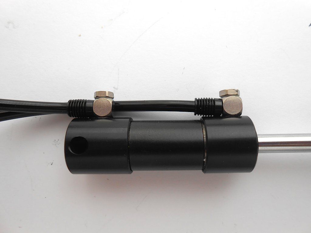 Next is the connecting rod. (it mounts the other way around from how shown) 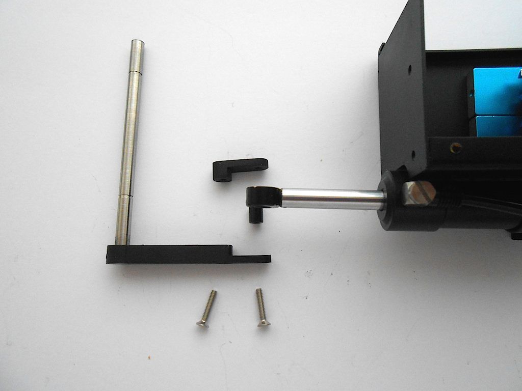 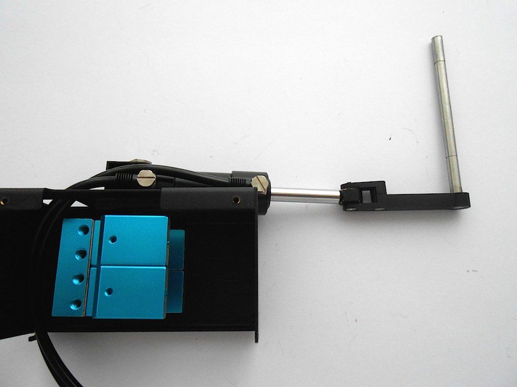 Then the actual kicker, that will have to slide over the rod when we install it in its proper position. (The kicker has to be horizontal when cylinder is completely out.) 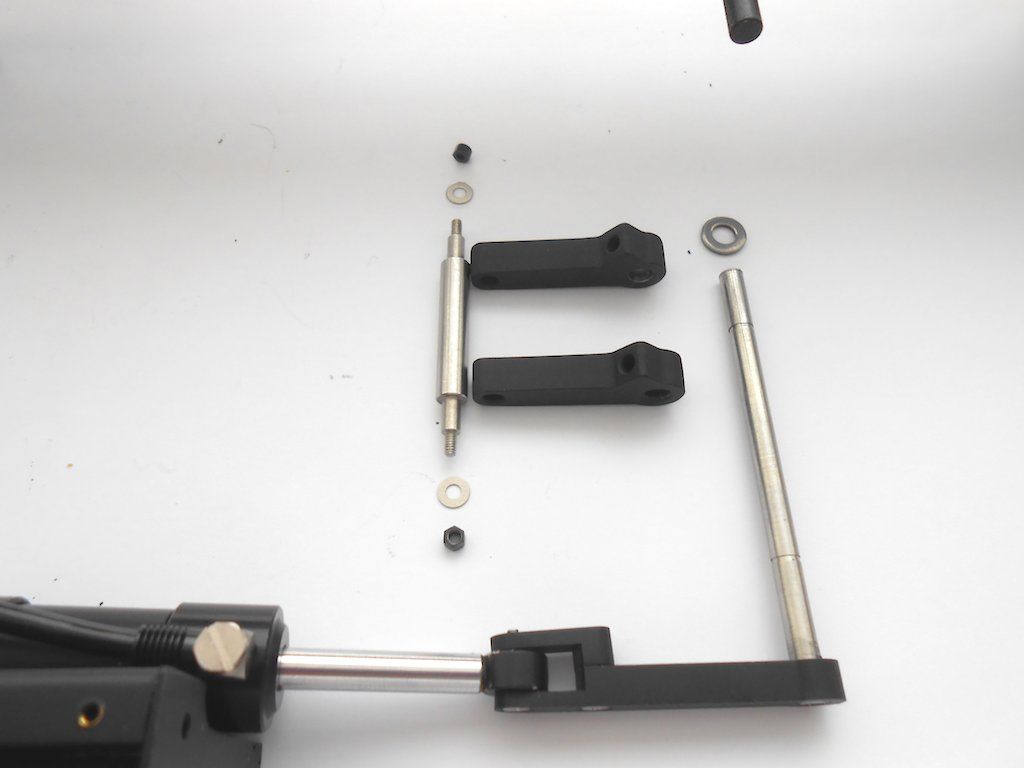 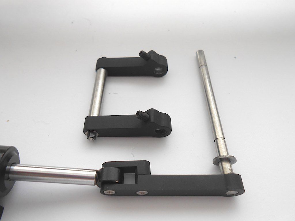 Then slide the assembly into the frame through the holes provided in the sub frame. (had to ream out the holes a bit due to the paint that got in) 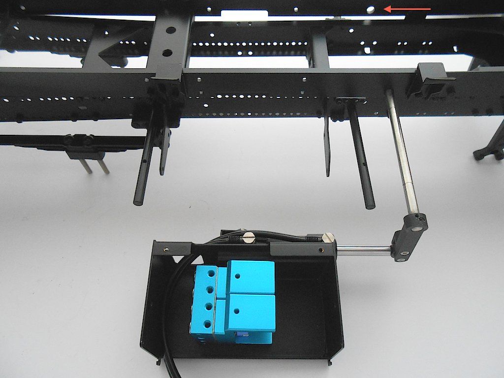 The valve box needs to be attached with 4 M2x5 screws to the box holders on the frame ... one of them is a absolute pain due to no room at all. 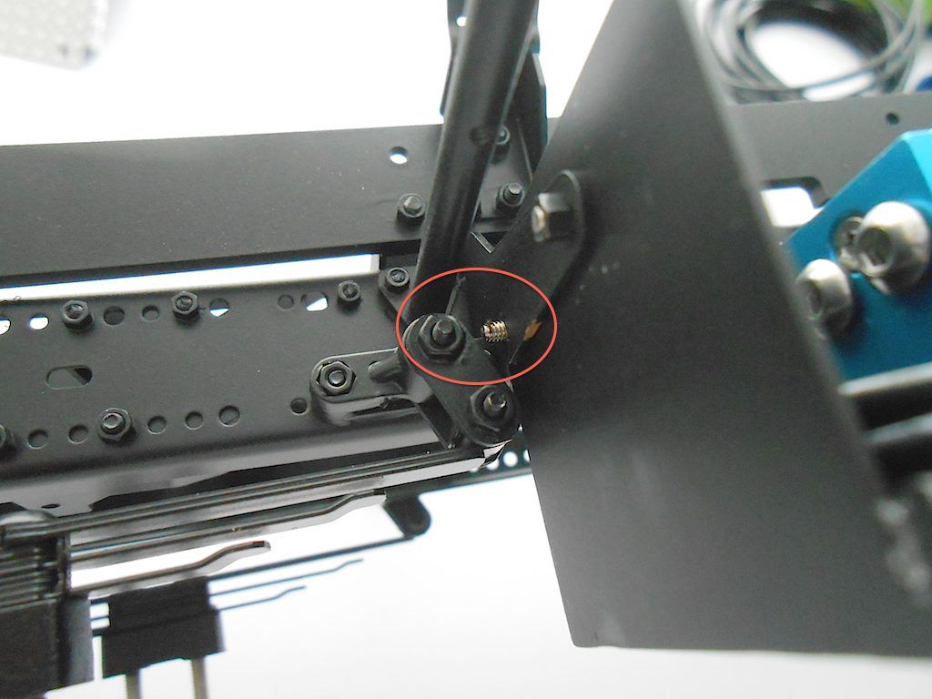 Here all installed (including above nut and screw) seen from the left. I also installed the 2 rubber bumpers. 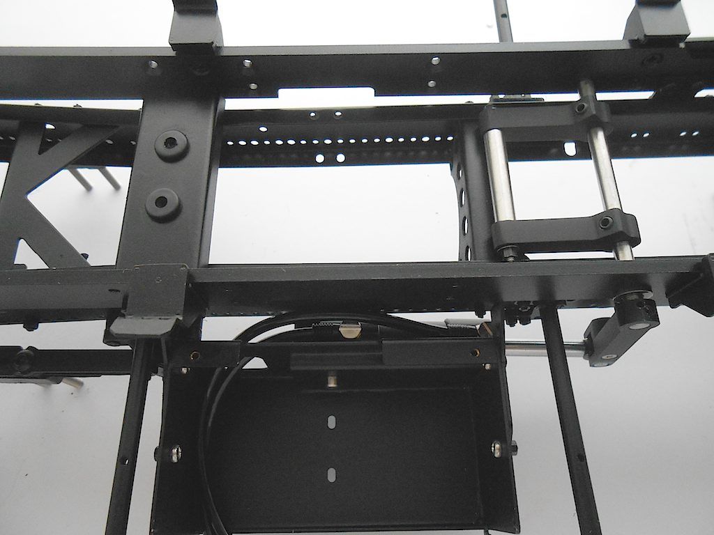 Here from the left. Rod that holds the kicker is secured with an M3. 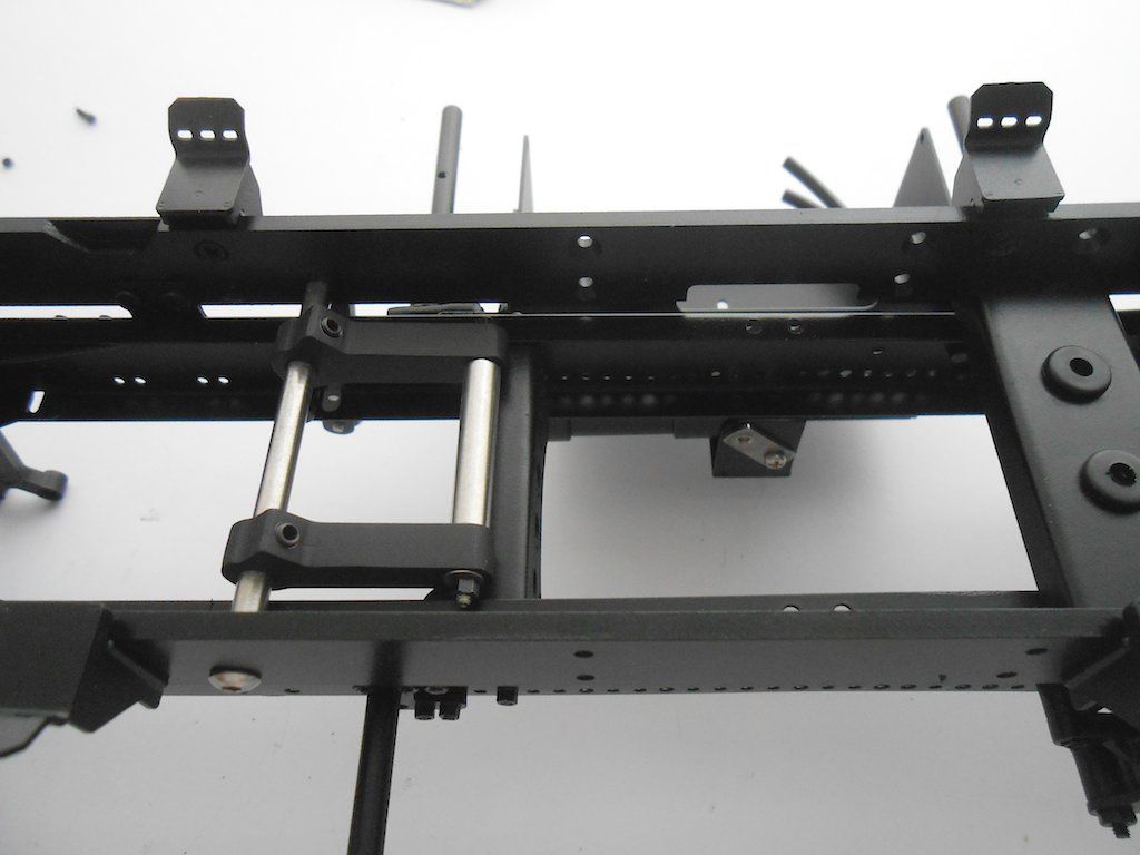 Last part was bolting the diamond plate cover to the valve box cover. 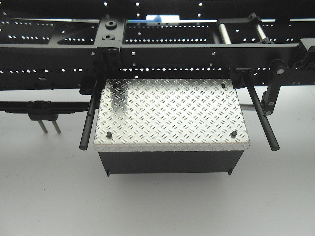 That's it for now. Cheers! Stephan Last edited by Rakthi; 05-22-2015 at 04:26 AM. |
|
#3
|
||||
|
||||
|
The rear lights are on the program next. (the orange of the indicators has to be painted in - used Tamiya X-26 for that)
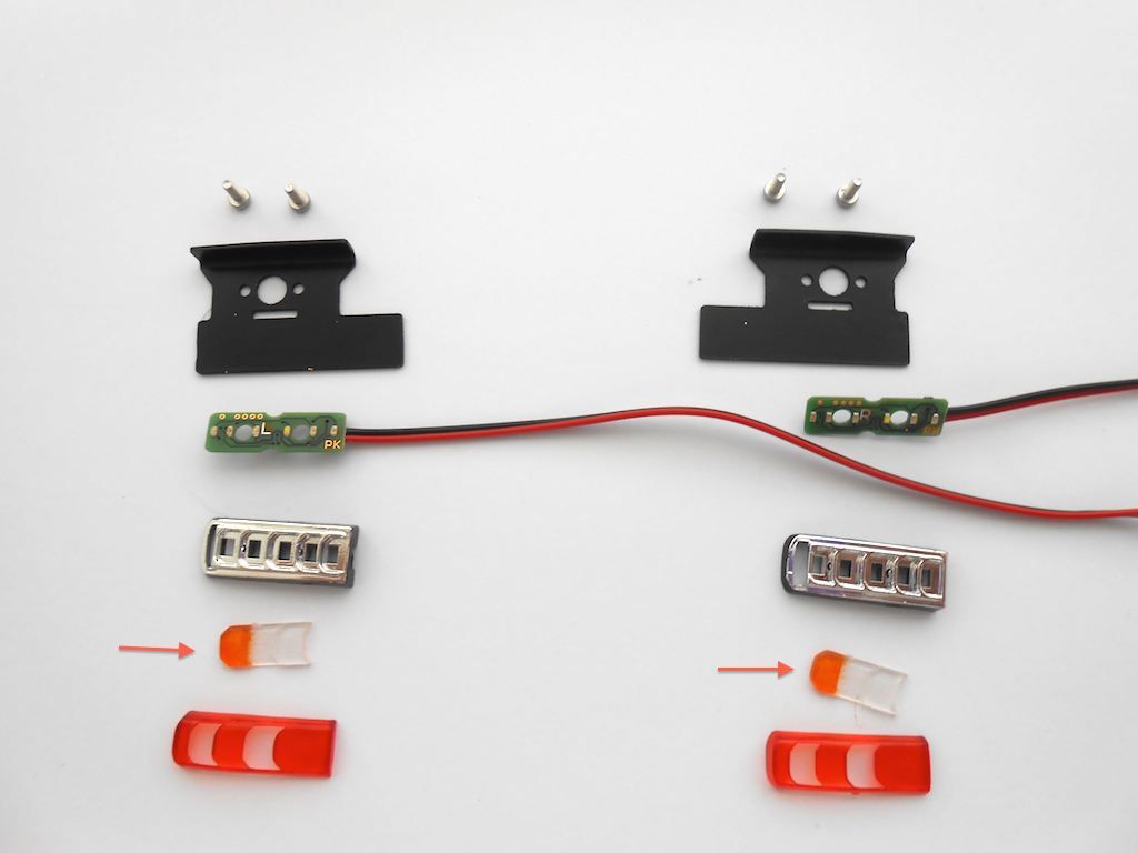 I ordered the kit with the KingBus system, so I only have two cable on each light. The cable is supposed to go in the inside of the frame, however a slight problem: This little plug 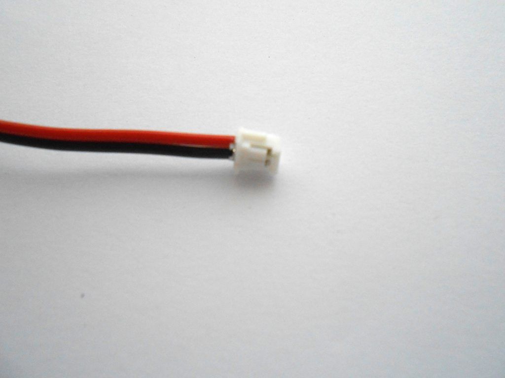 Does not fit in the round hole, more so because the lower rear crossbeam sits further back and blocks part of it. 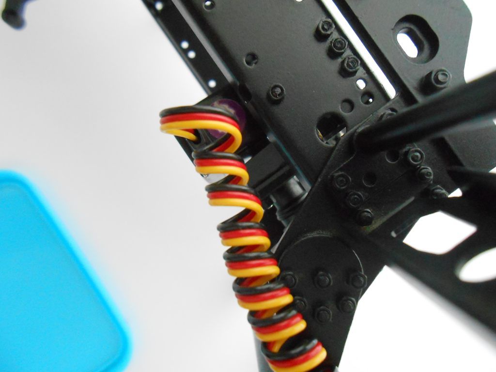 The plug does reminds me of the ones I had on my motorbike. And those would come apart with some fiddling. Took me a bit, but if you get a needle you can lift up the little plastic tabs and pull out the cables ... not a fun job the first time around, but easier if you lift the tab from the top between the 2 tabs. 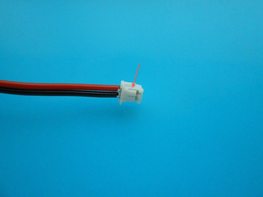 Bare cables. They only go one way back into the plug. The little edge pointed out by the arrow is what holds them in place. 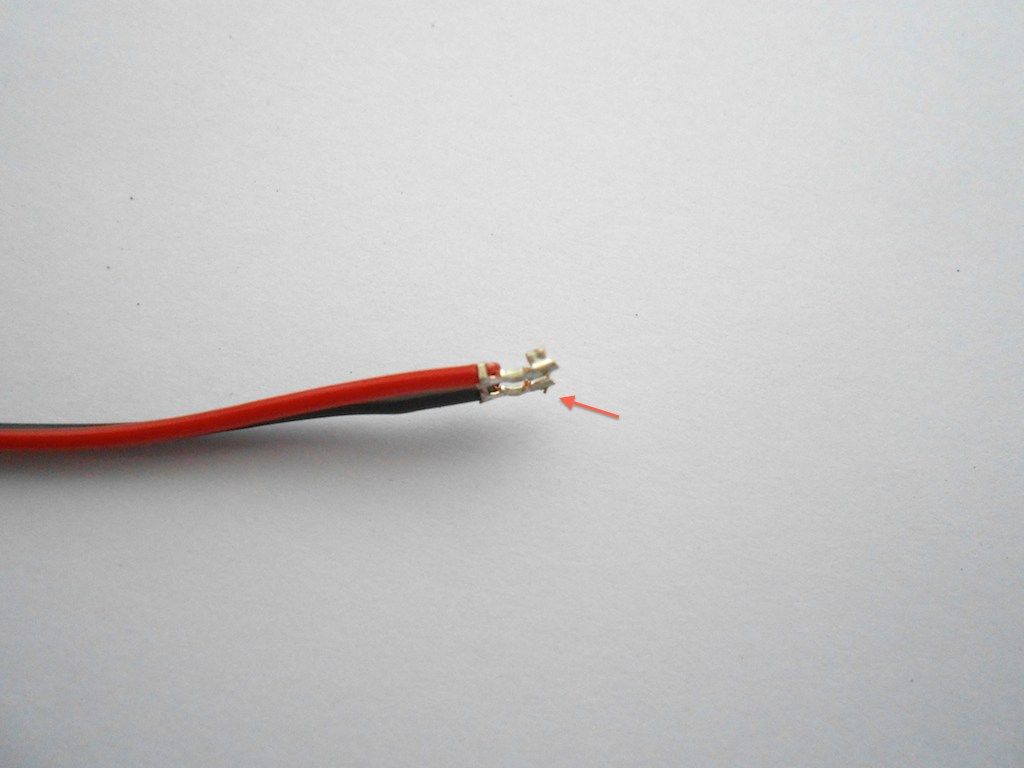 This sorted, next we have to cut a small channel in the plastic body of the light fixture. This to accommodate the cable. 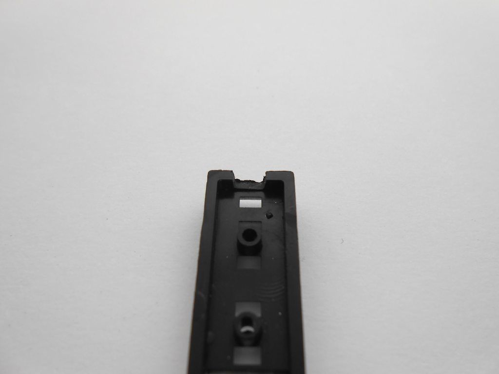 Need to carefully smoothen the edges of the LED board so it fits into the housing. (I used 800 grit paper for this) 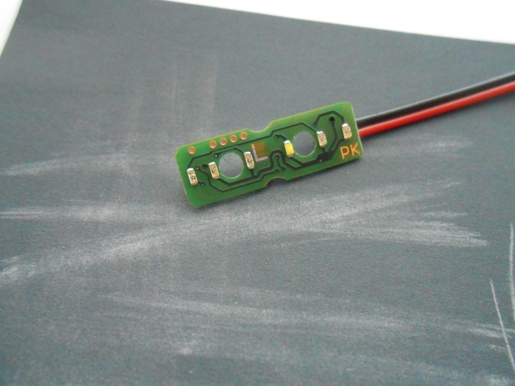 Now fits nice and flush in the housing 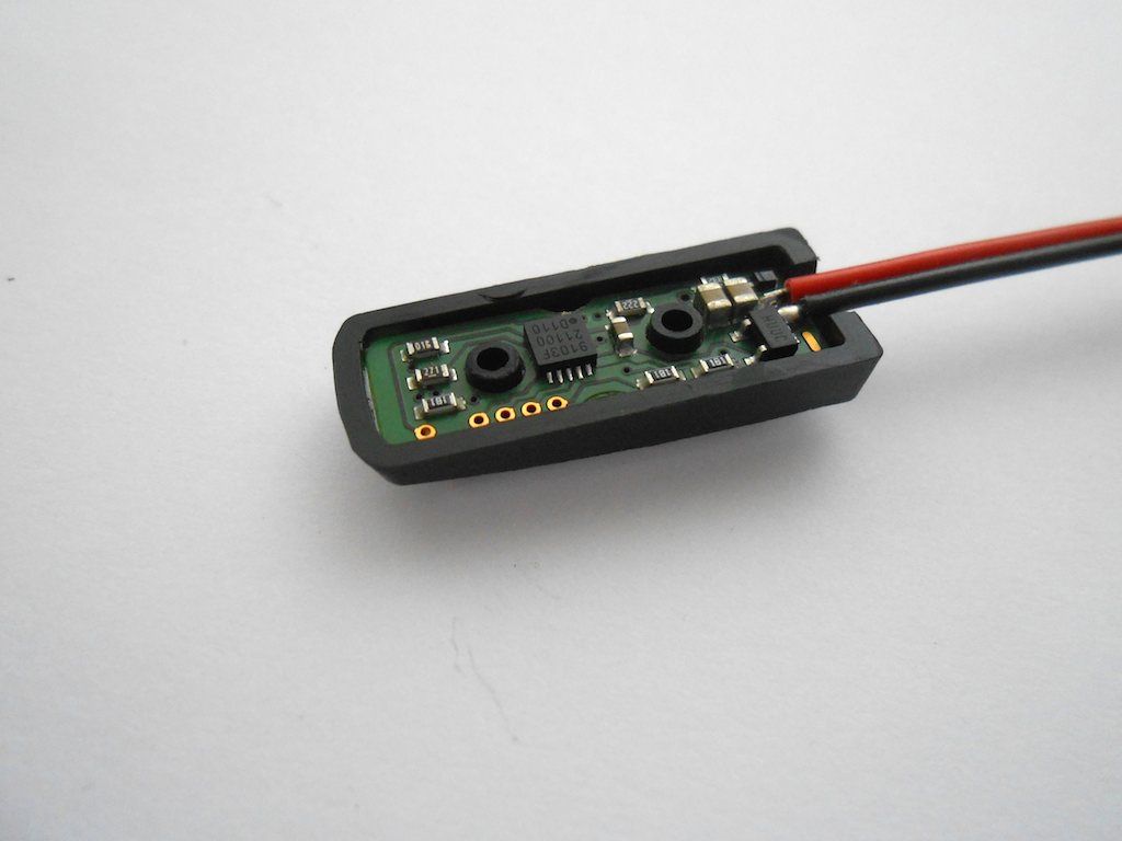 Added some heat shrink over the wires and cut an insulator from an old inner tube. (there was supposed to be one with the LED board but didn't see it) 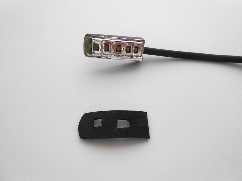 Fed the wire through the hole into the frame - had to take the servo out to make it easier - and in hindsight made my life difficult due to being so focussed on getting the wire in the frame ... 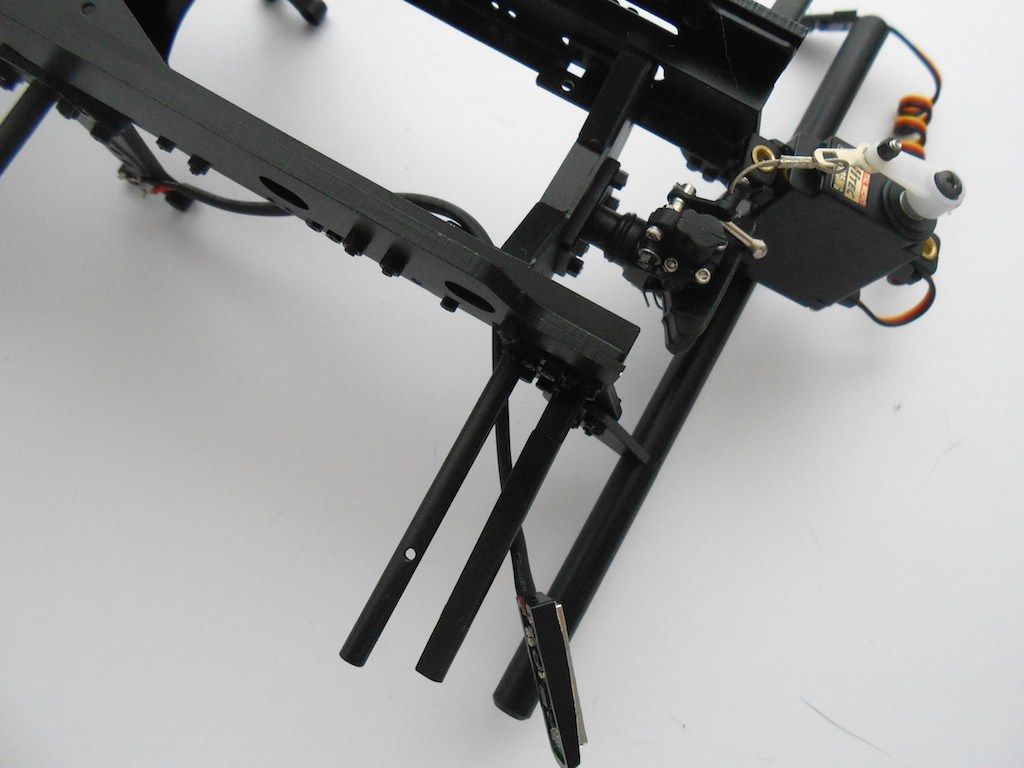 Tried to fasten the M2x5 screw indicated in the manual, but it didn't fit. 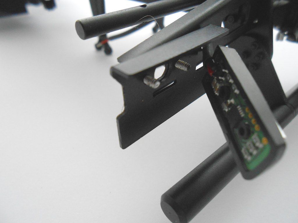 The holes provided are for M1.6 screws, so changed to those. 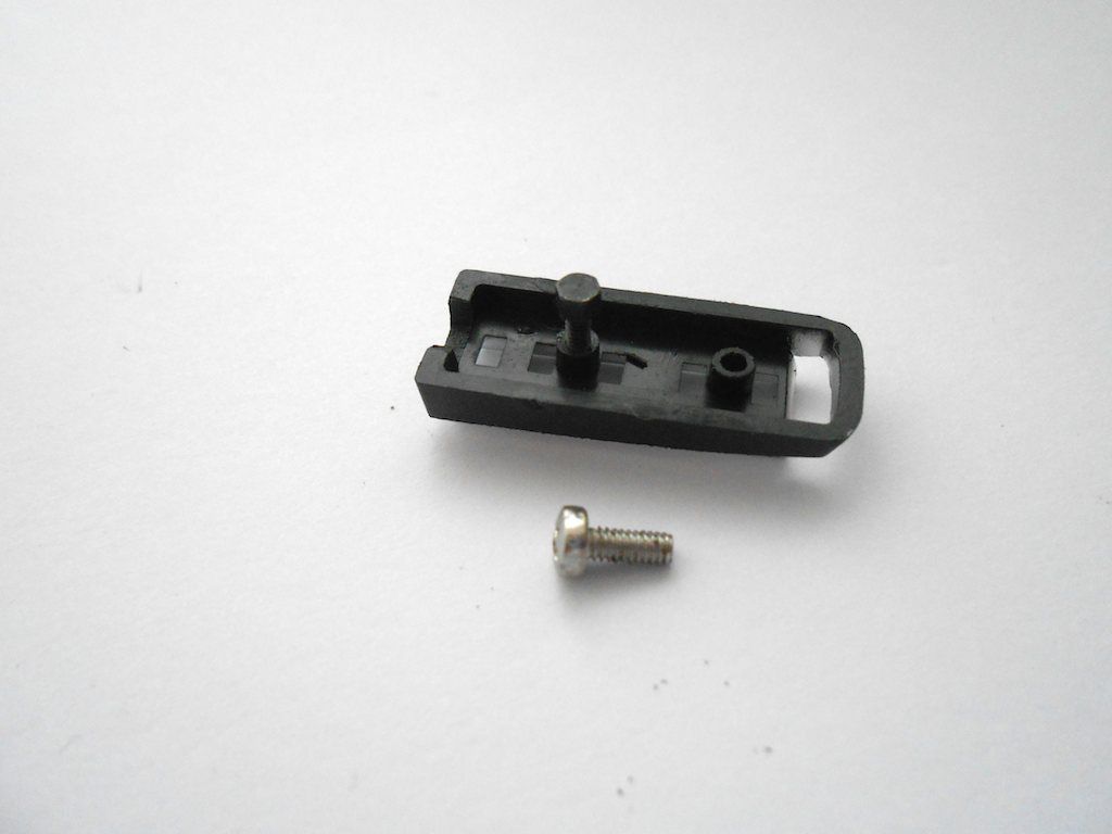 Light fixture installed 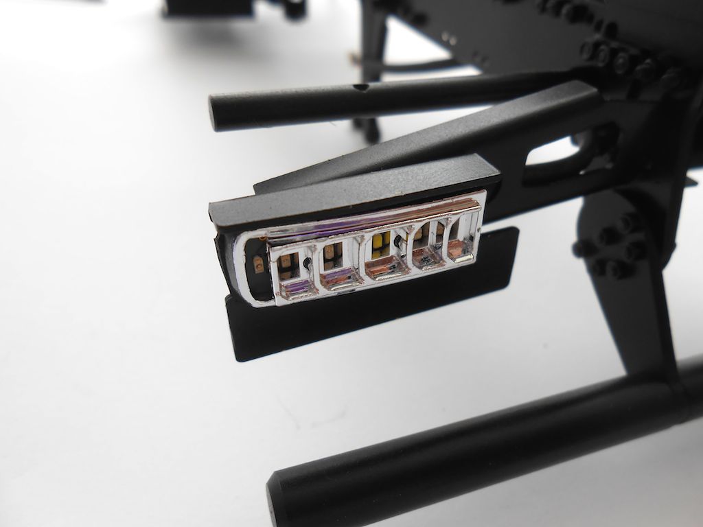 Plug back in place 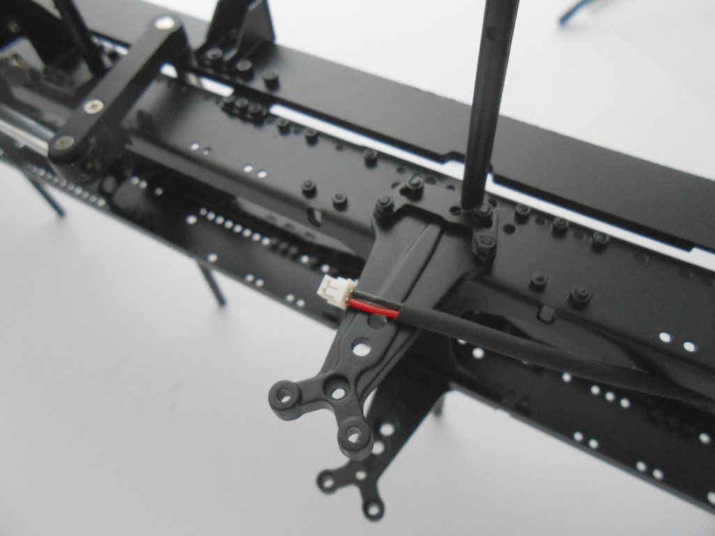 Servo back in place and lenses glued in place with 2 component transparent glue. 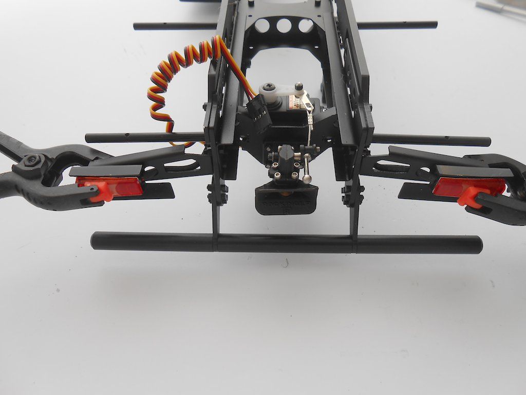 Cables tucked in the frame for now 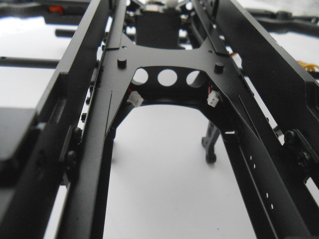 And here a pic without the clamp 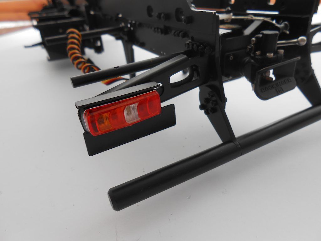 If I had to do this again, i would first fix the light to the support, then add the heat shrink and feed it in the frame. Oh well ... |
|
#4
|
||||
|
||||
|
Some more parts that need be bolted to the frame before starting on the drivetrain.
First, the housing for the servo diff lock front axles. The manual indicated 5 M2x5 but only need 3. 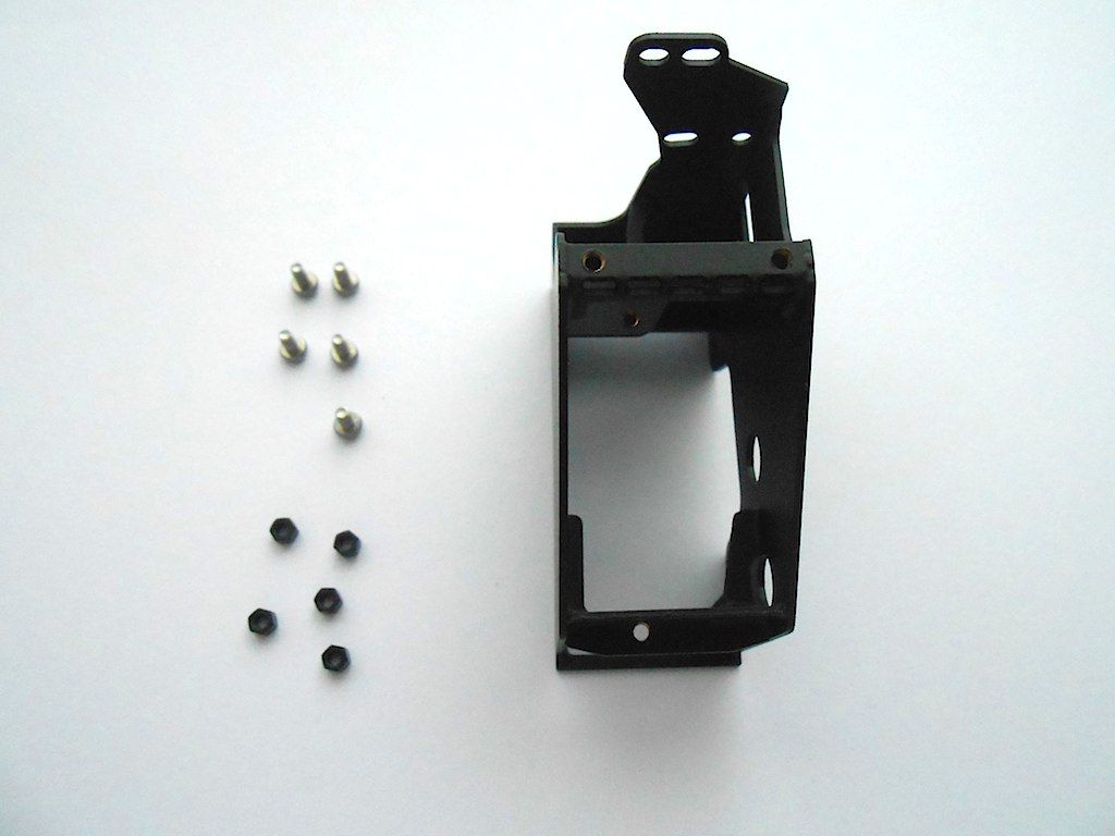 This is another one of this little gems that make you realise how much thought and care goes into these models. Even for a part that you don't really see once the truck is build. (Yup I can get carried away by things like this) 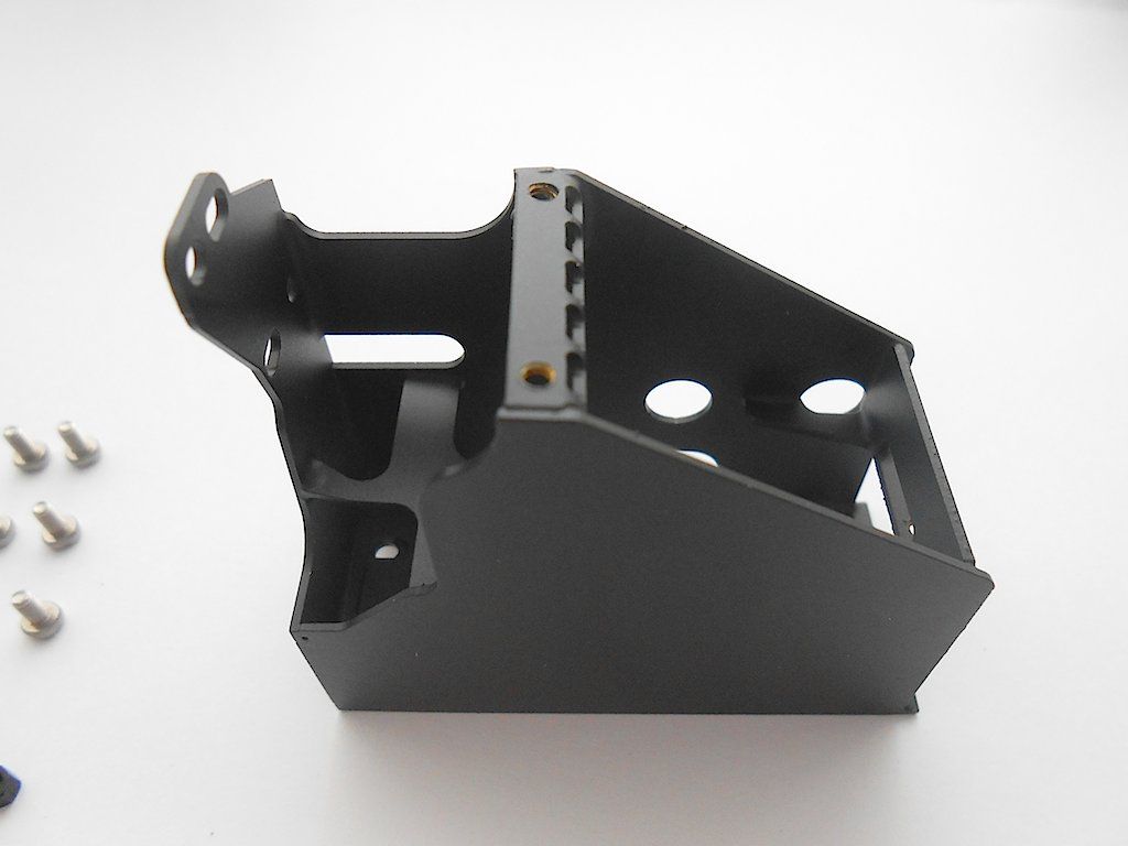 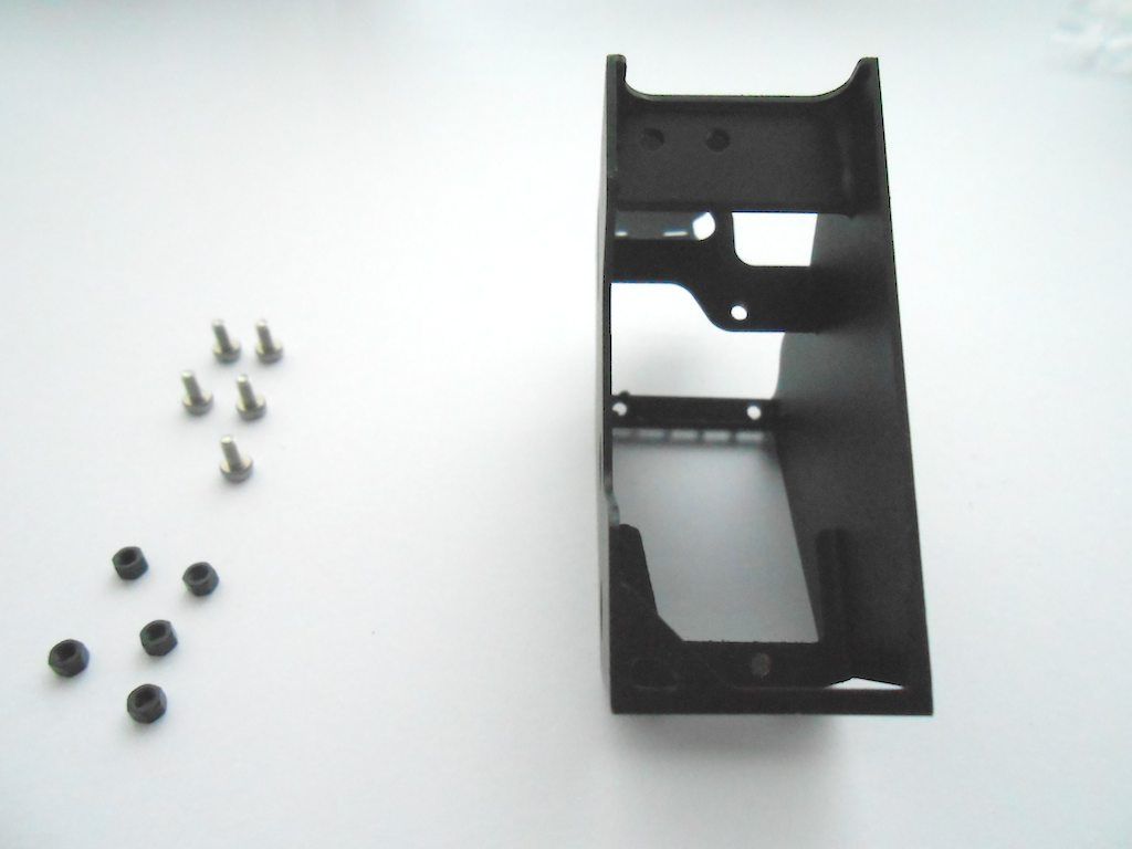 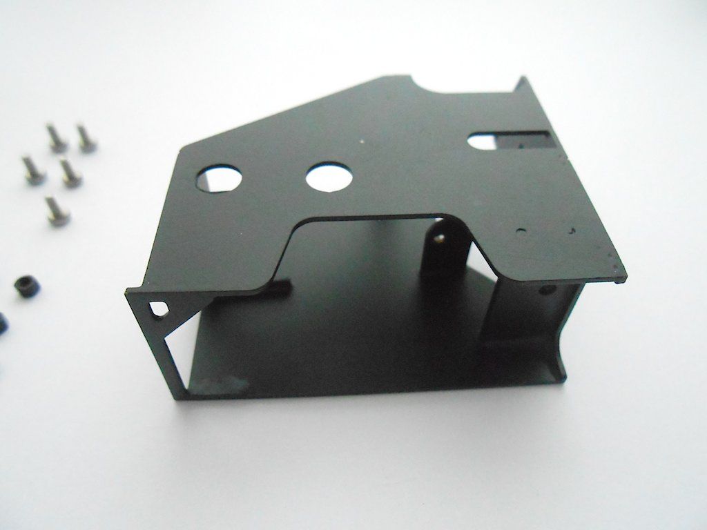 Goes here, right behind the cab. 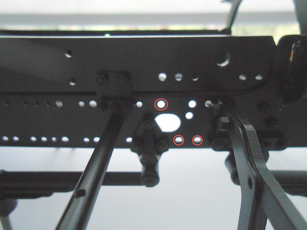 Neat fit. 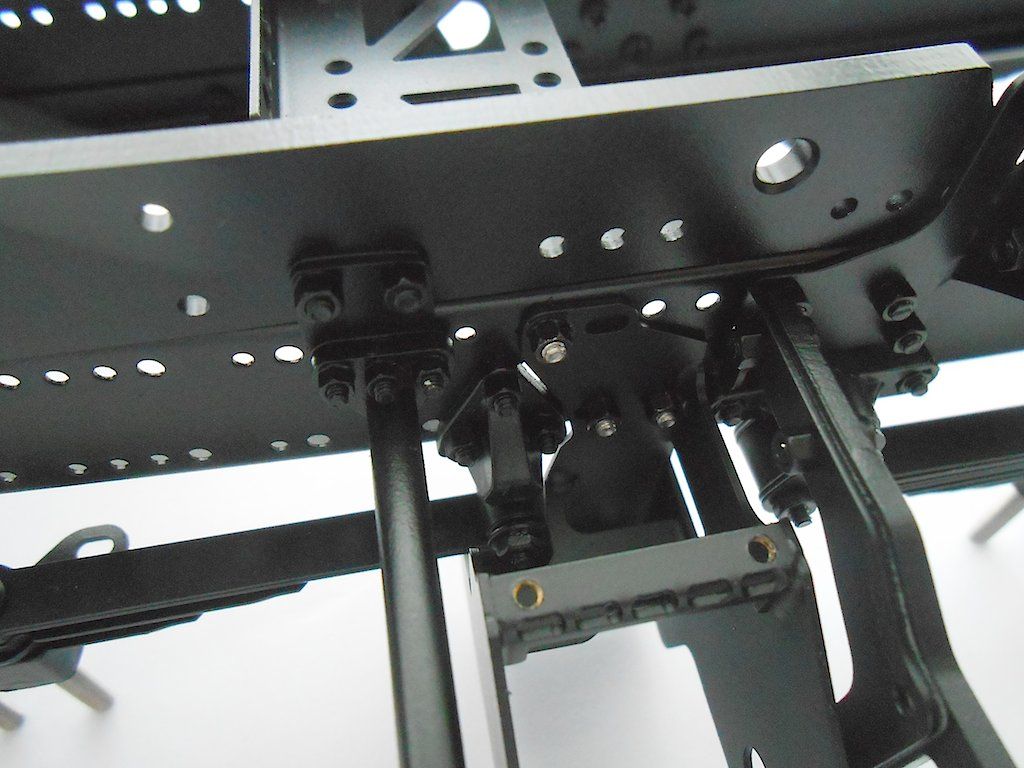 Looks like I better bolt that bit from the cabin fender on before I install the servo.   Upside down view from the back. 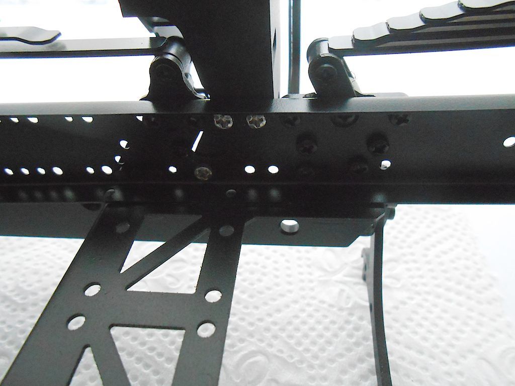 Next are the supports for the oil pump and tank. 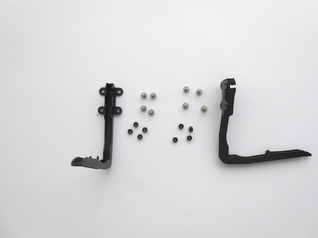 Goes here, which is kind of a problem because on the left, there are bolts from the middle cross beam ... I should have paid more attention to that section. 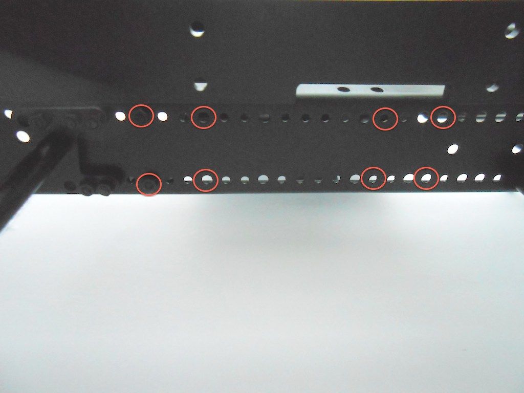 They came out easer than I thought. 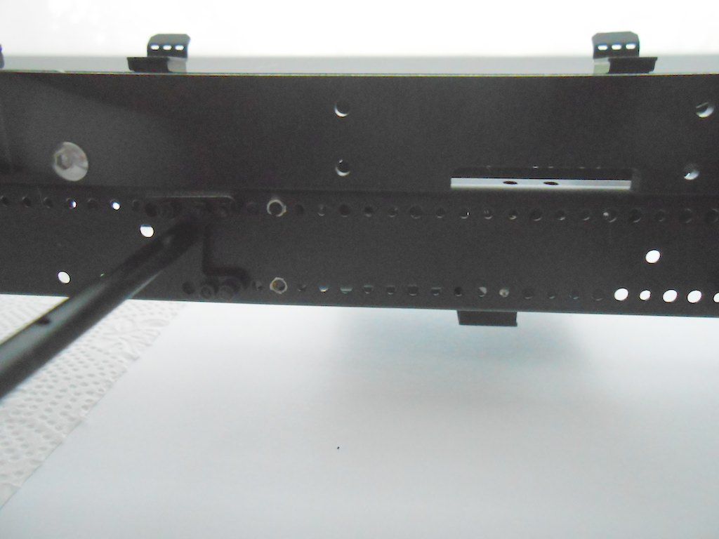 And tank supports installed ... the left bottom screw took me more than 20 minutes to get into the hole. Almost no access with the valve box and kicker mechanism in place ... There is a reason you're supposed to install it way earlier in the game. 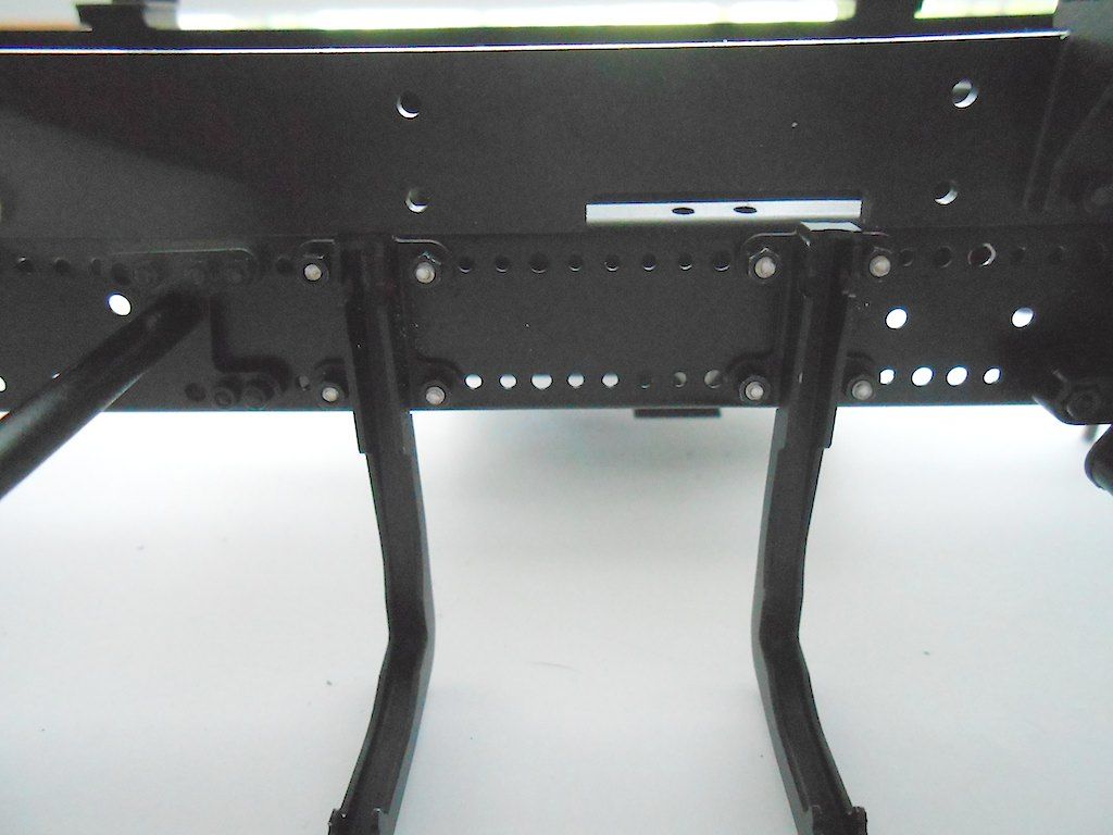 I put the tank in place. You can see that the supports are not really symmetrical. 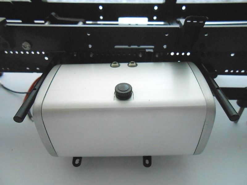 Reason why the supports are not evenly spaced is the outlet from the pump. That bolt will be replaced by a nipple with a 4mm oil line attached, so you need some room. 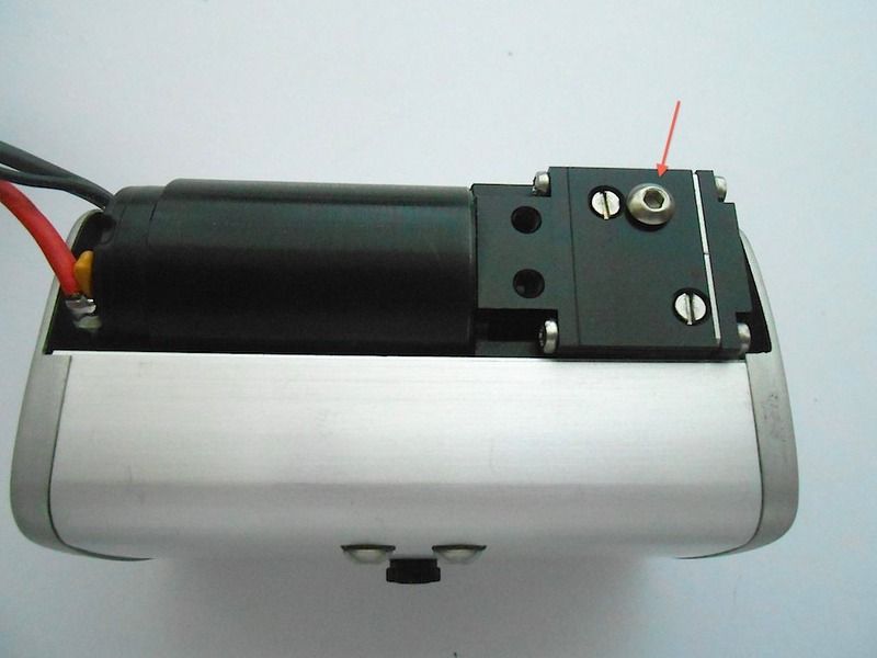 Looking from the back it seems I could get away with moving that support one hole closer to the front. 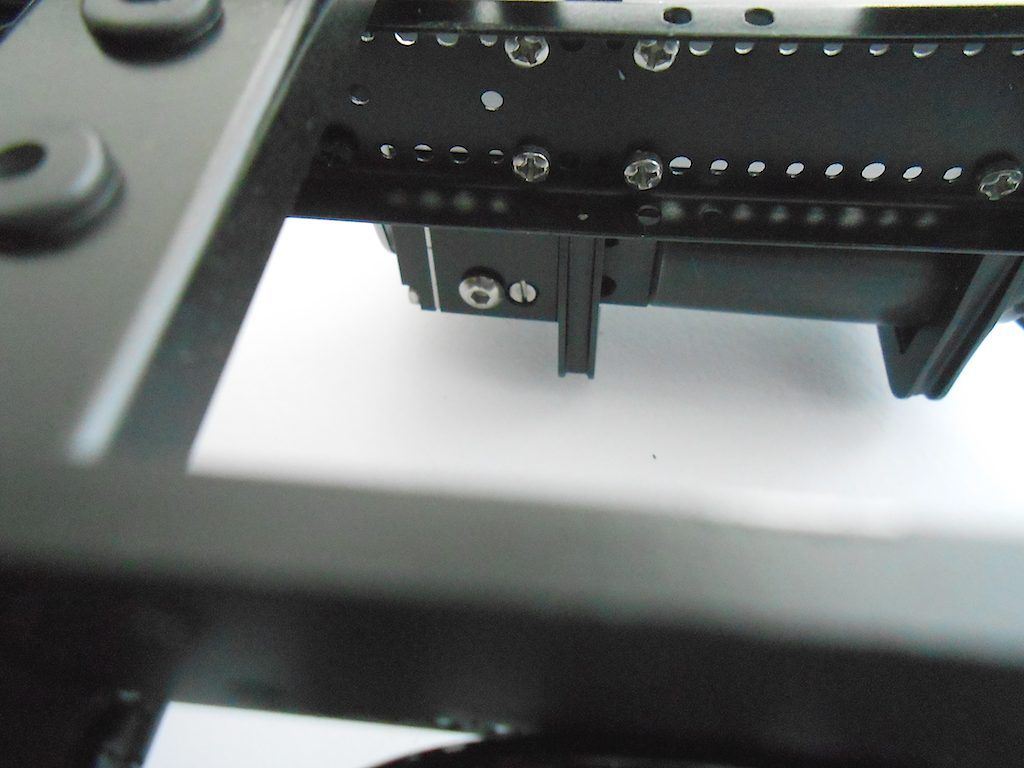 Cheers, Stephan |
 |
| Tags |
| 8x8, arocs, scaleart |
| Currently Active Users Viewing This Thread: 3 (0 members and 3 guests) | |
|
|