
 |
|
|||||||
| Euro Style Trucks and Trailers A place for the Euro style trucks single and twin axle trucks and trailers... |
 |
|
|
Thread Tools | Display Modes |
|
|
|
#1
|
||||
|
||||
|
Spend time on the transferbox lock.
The steel cable goes into a teflon one that goes into the metal guide ... Here a picture of what I'm talking about. (just for show) 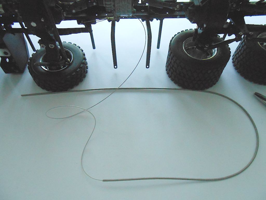 Cutting the servo horn and drilling the 3rd hole out to 2mm etc. 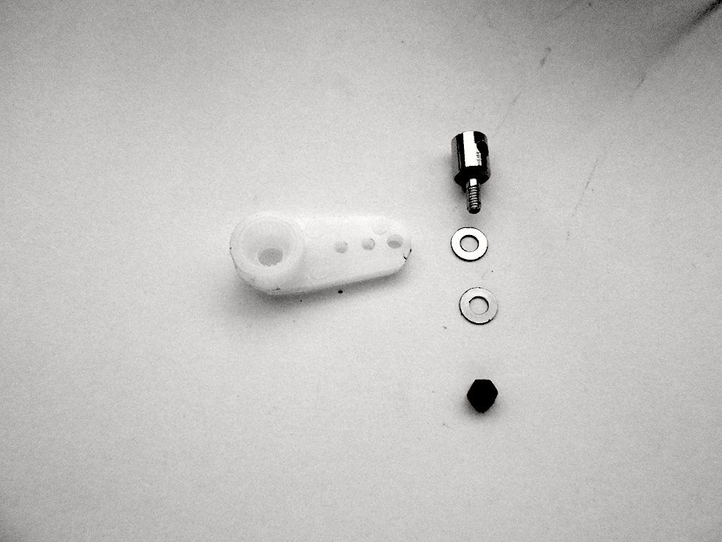 Decided to make the horn black with a Sharpie before I mounted it on the centered servo. (looks reddish in picture, but is black) 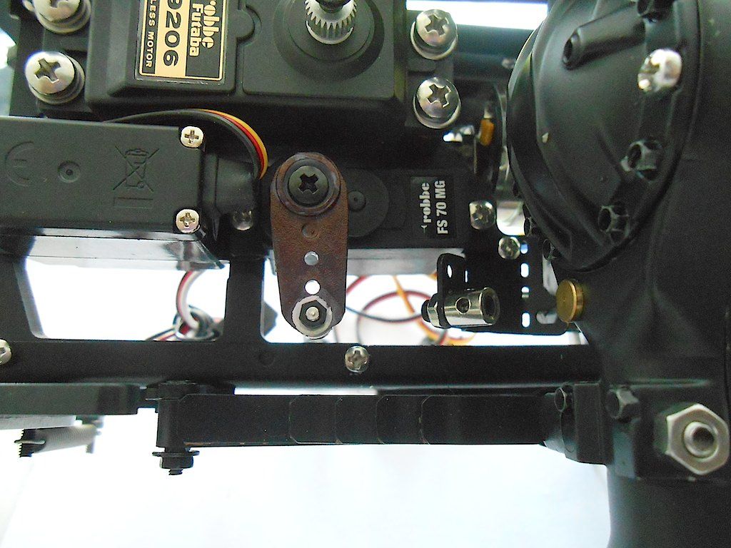 Then I spend some enervating time figuring out how to run the metal tube. First I started out at the transferbox and worked my way forward, but that was a non working proposition because trying to get that flippin thing in the clamp near the servo is a nerve wrecking proposition ... Well anyway now had a good idea of how to fit it. So started from the servo and worked my way backwards to the transfer case. Shortened it there and gently clamped it in place with the screw. Then shove in the teflon hose, followed by the steel pull cable. After I finished this bit, I took pictures of how I ran the cable. Starting at the transferbox the cable goes towards the rear of the truck. 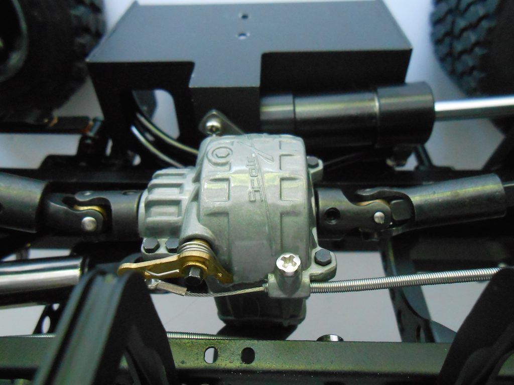 There it goes inside the frame through one of the holes provided and swoops 180° back towards the front. I have attached to of those clamps, but I drilled the hole out to 2.5mm to make it easier to get the cable through. It does not clamp the cable, just prevents it from flopping about. 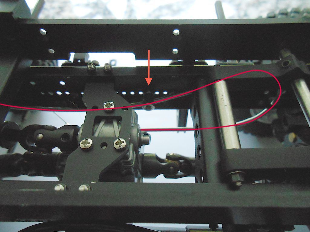 Installed a 2nd clamp (also drilled out to 2.5mm) just before the gearbox, and from there the cable swoops up to go over the gearbox 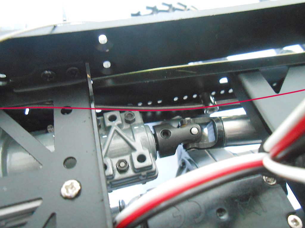 And then down again to the clamp near the servo. 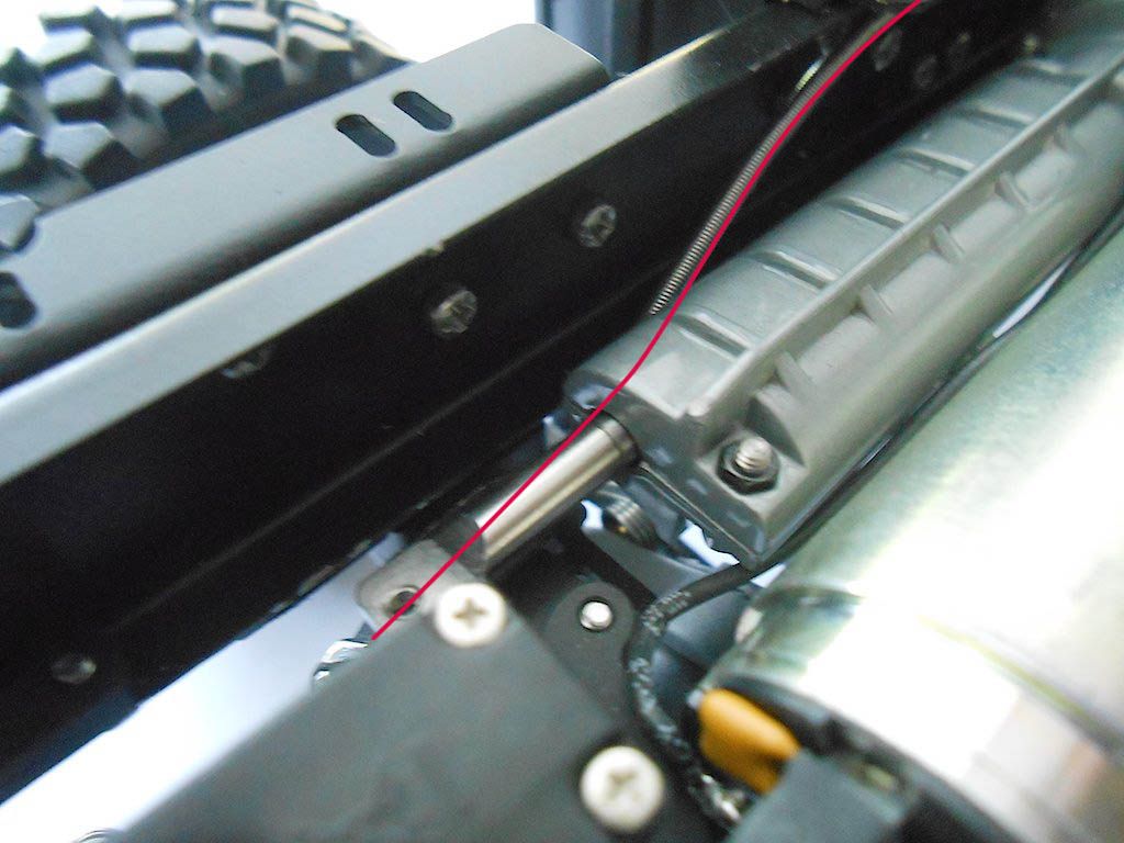 There the metal and teflon hose are cut to size and the steel cable is then tensioned and attached to the servo. I haven yet cut the steel cable to size because I might need to make some adjustments once I get the radio control hooked up. The red arrow points toward where the next step - gearshift - will attach. 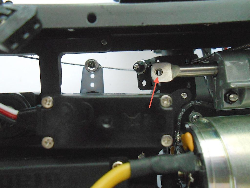 Gearshift - the parts 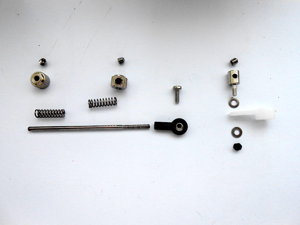 Easiest to first attach the pull bar (tried some other approaches first) 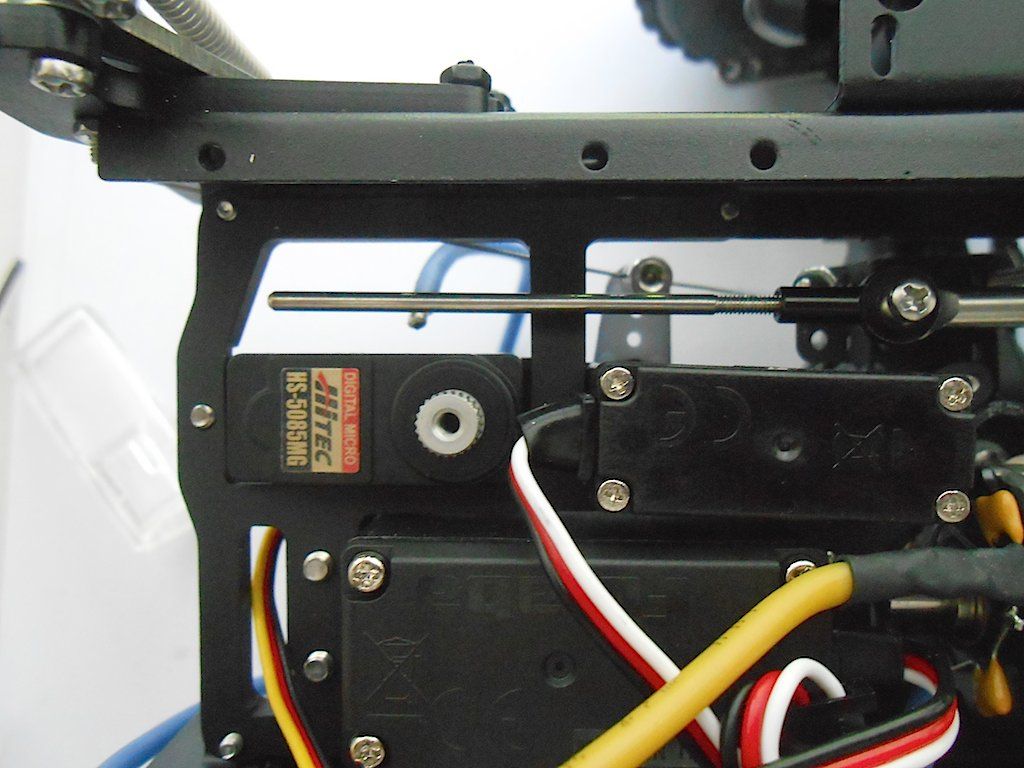 And then mount these bits. The clamp attaches to the servo horn pointing downwards. They show it mounted both ways in the manual. 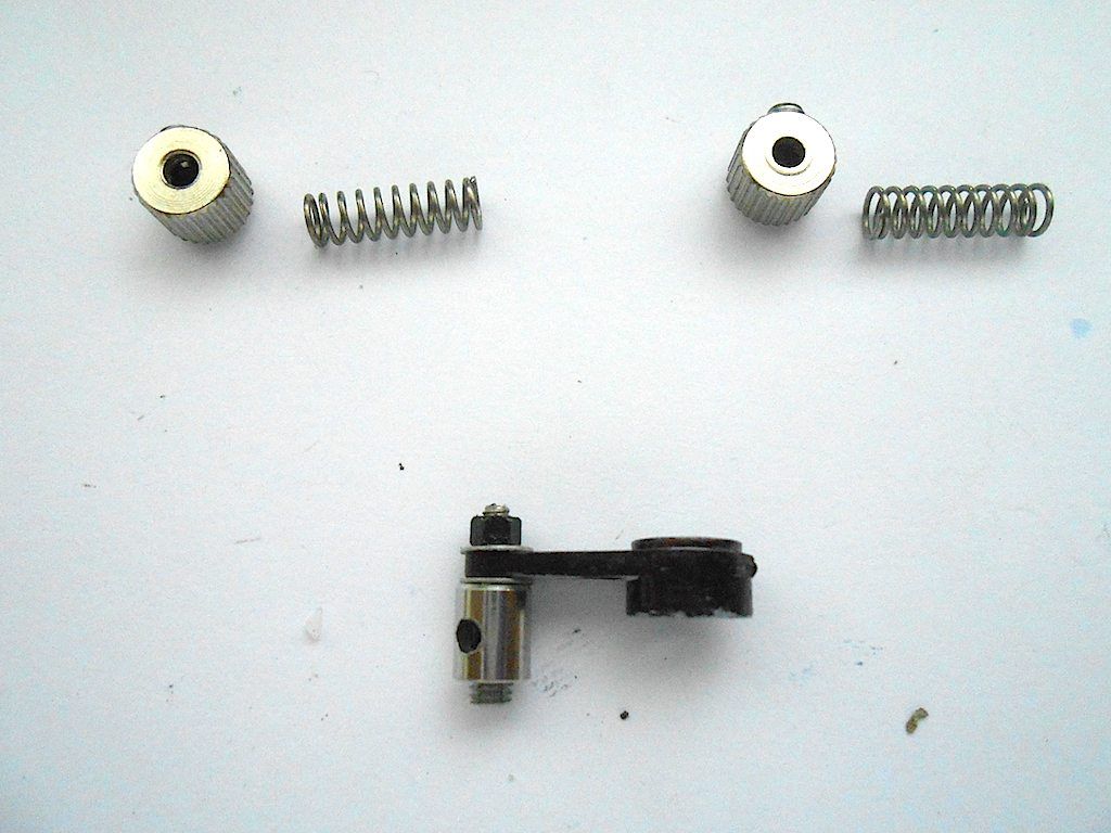 Installed. There is a mark on the bit sticking out from the gearbox that indicates 2nd gear. (This is installed with the box in second gear) The springs are supposed to be only lightly compressed. (careful, I spend about 10 minutes looking for the one that sprung away) 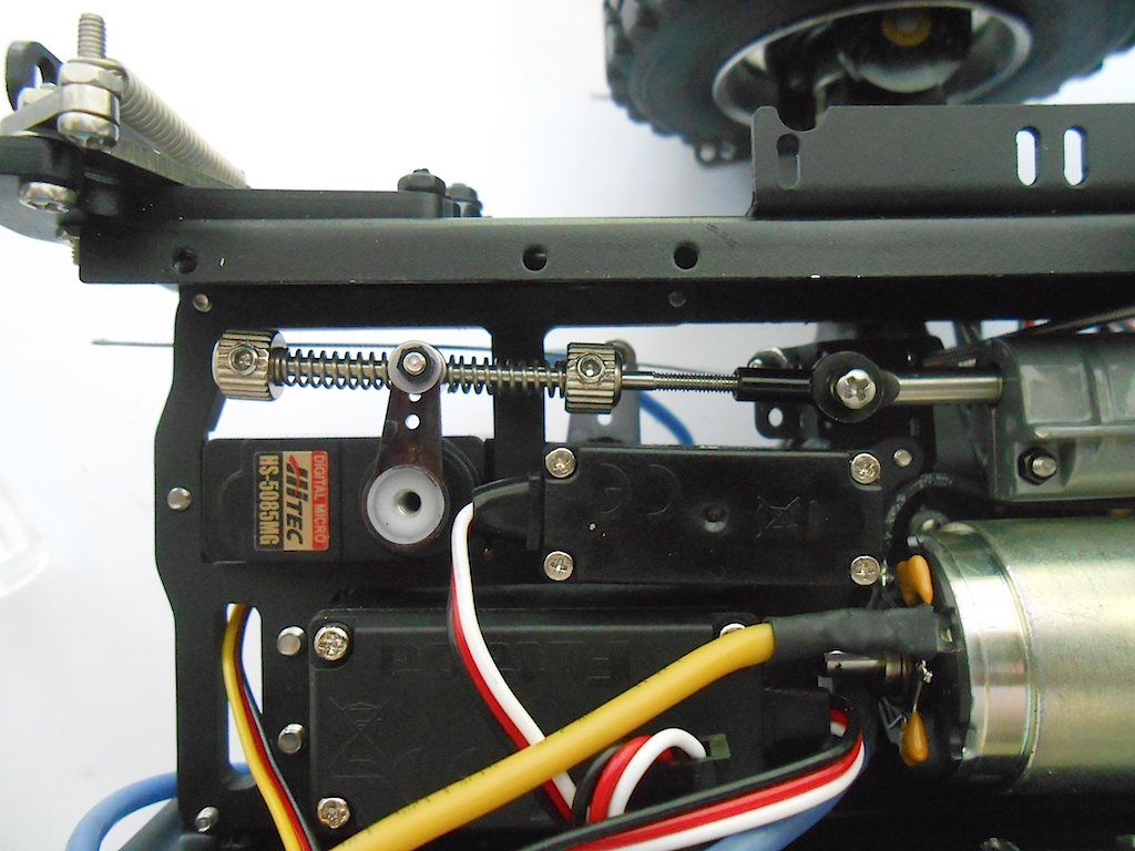 And last the steering linkage 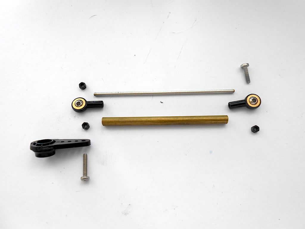 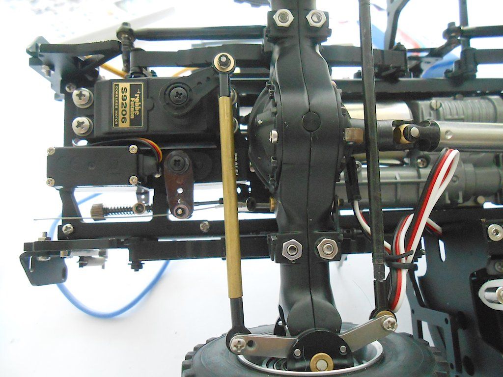 Now next would be the bowden cables of the diff locks of the axles. Hope they go in easier than the transferbox one.
__________________
Cheers, Stephan (Rakthi is the one in the avatar) |
|
#2
|
||||
|
||||
|
After yesterday's trouble with the bowden cable I was prepared for another ordeal. However it all turned out to go rather easy.
First attach the bowden pull tube to the axle and guide it to the clamps that were installed way back and guide it through the frame to the clamps near the servo. 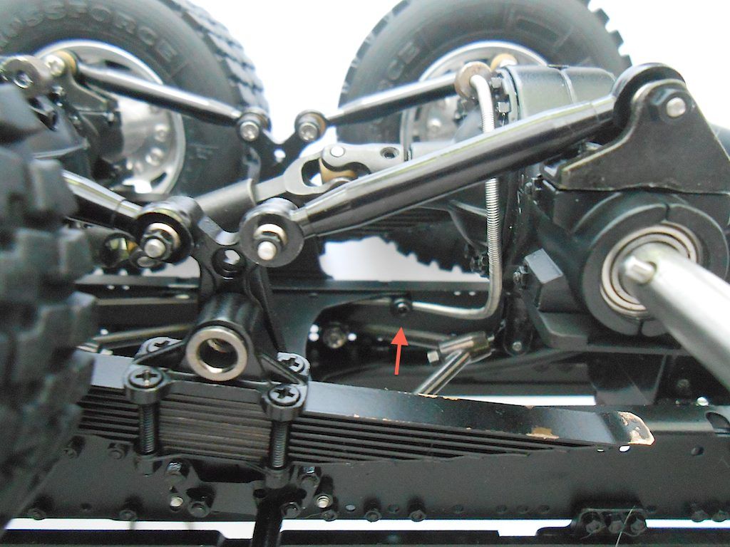 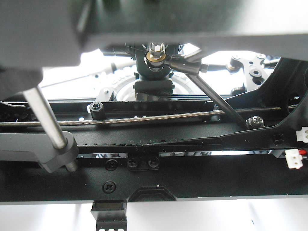 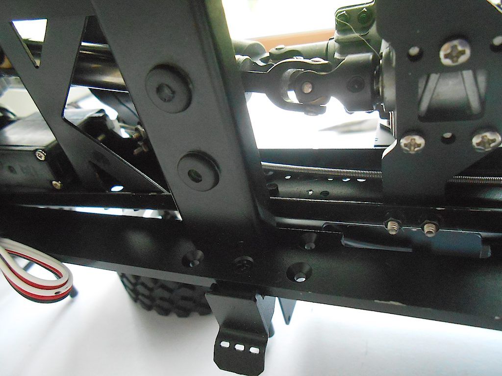 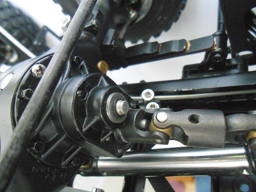 Then insert the steel cable, make sure it moves smoothly. Then cut bowden pull cable to size. 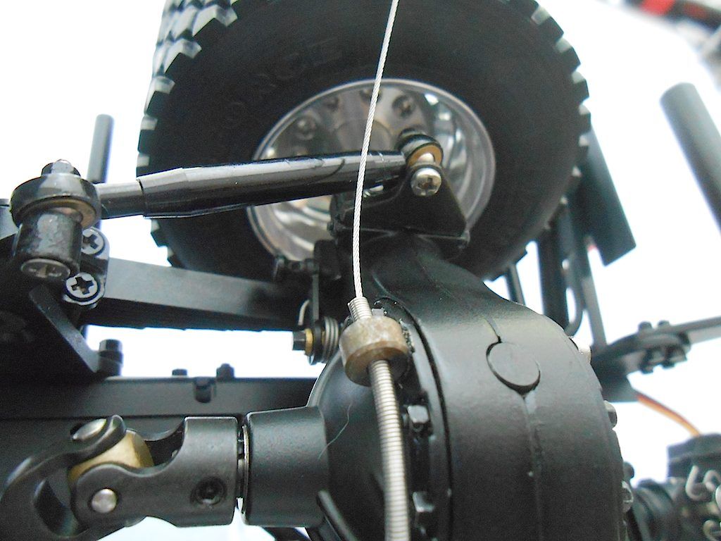 Attach steel cable to the puller on the axle - I used a loop there before I put in the screw - and push cable till it comes out at the servo. (If I do this again, I will insert a screw in there before I even mount the axles to the frame. Saves a lot of fumbling) 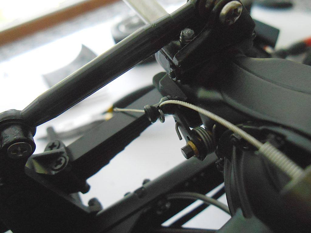 For those who wonder how the bowden is clamped in place on the axle: The hole through which the tube goes is attached with a screw. You have to loosen this one a bit so you can push the hose through. Afterwards just tighten a bit and hose is clamped in place without being crushed. 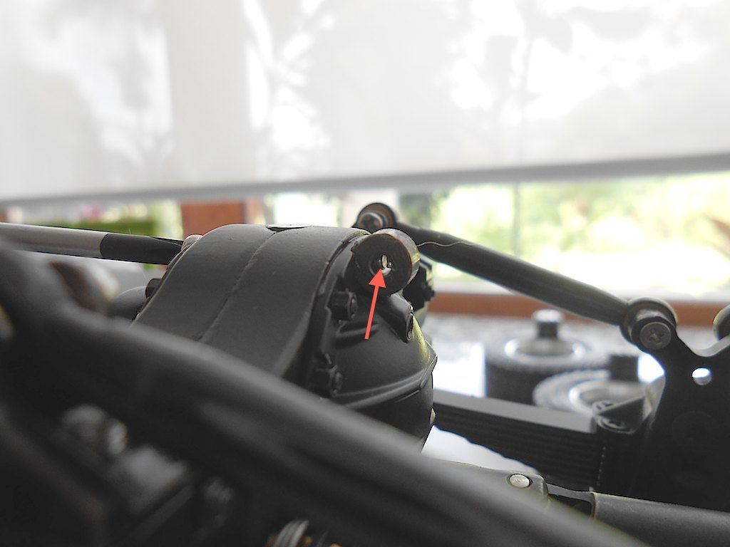 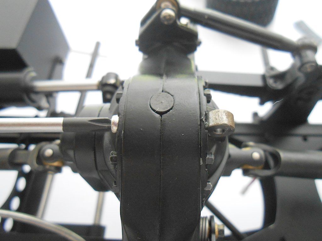 The next axle is same procedure 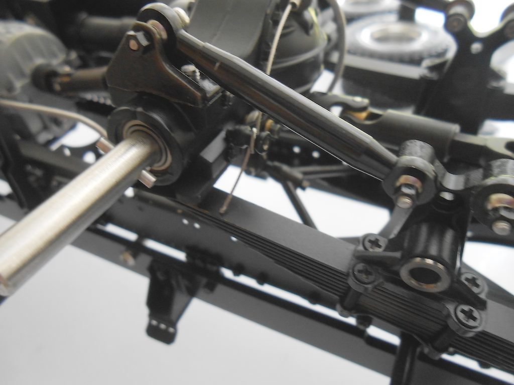 I first tried to run the pull cable through the indicated hole in the frame, but that just complicated things. So went straight to the previously installed clamp. 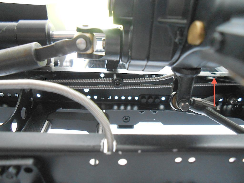 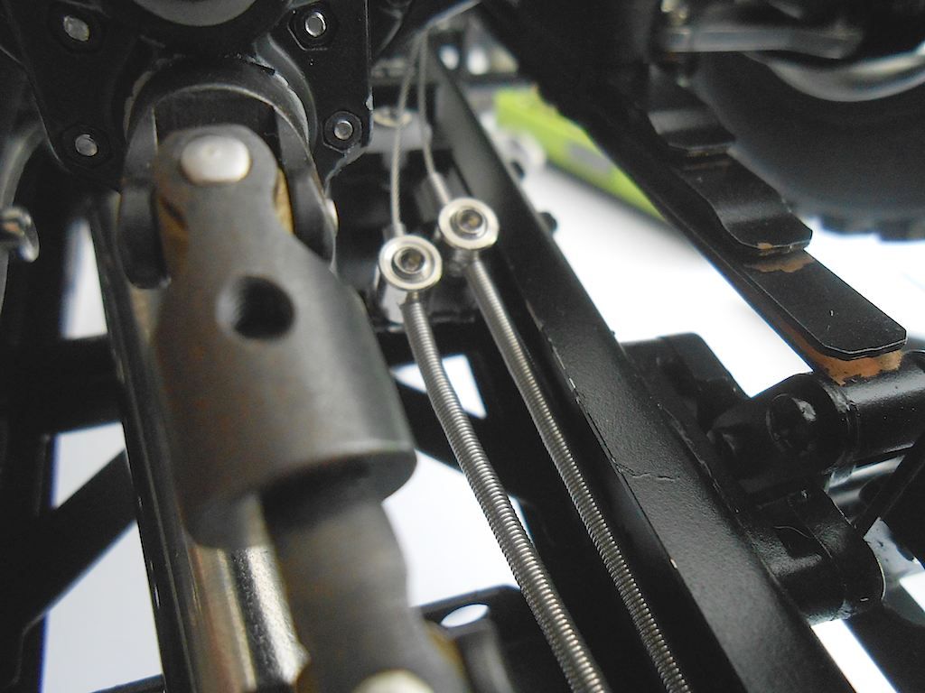 Tensioned up and eft some extra for possible later adjustments. Cut all the cable ends shorter and added a dab of crazy glue to stop fraying. 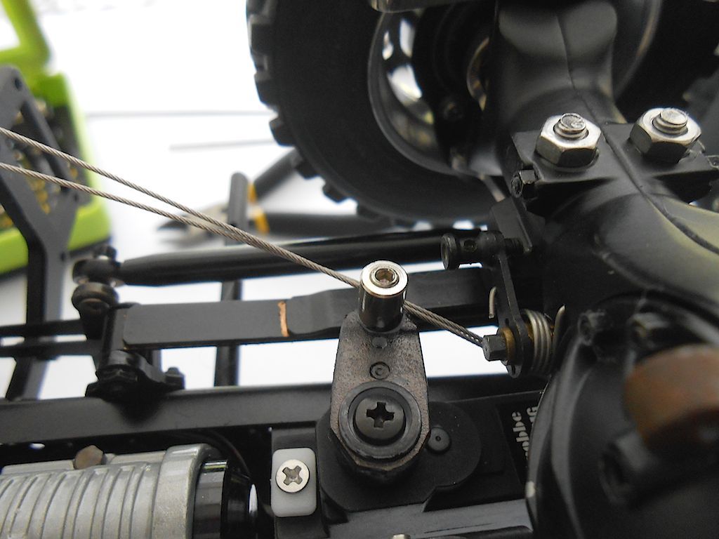 Was going to stop here, but then noticed that the left over bits from the rear axles were more than enough to do the front ones too. (so still have a complete set of cables from the front axles that should sufficient to redo the lot) Again same procedure, but routing is way simpler. (did have to take of the steering linkage for the 2nd axle to be able to get the the screw that allows the cable to be attached to the axle. Since it was off I also adjusted the tracking that was a bit off) 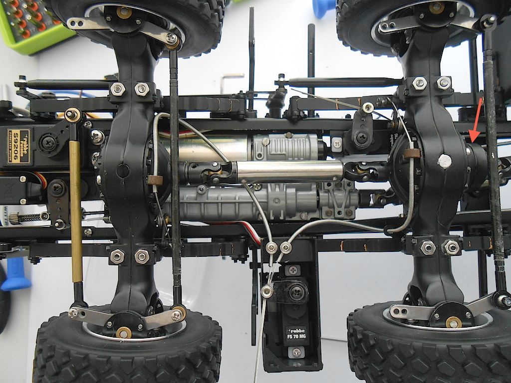 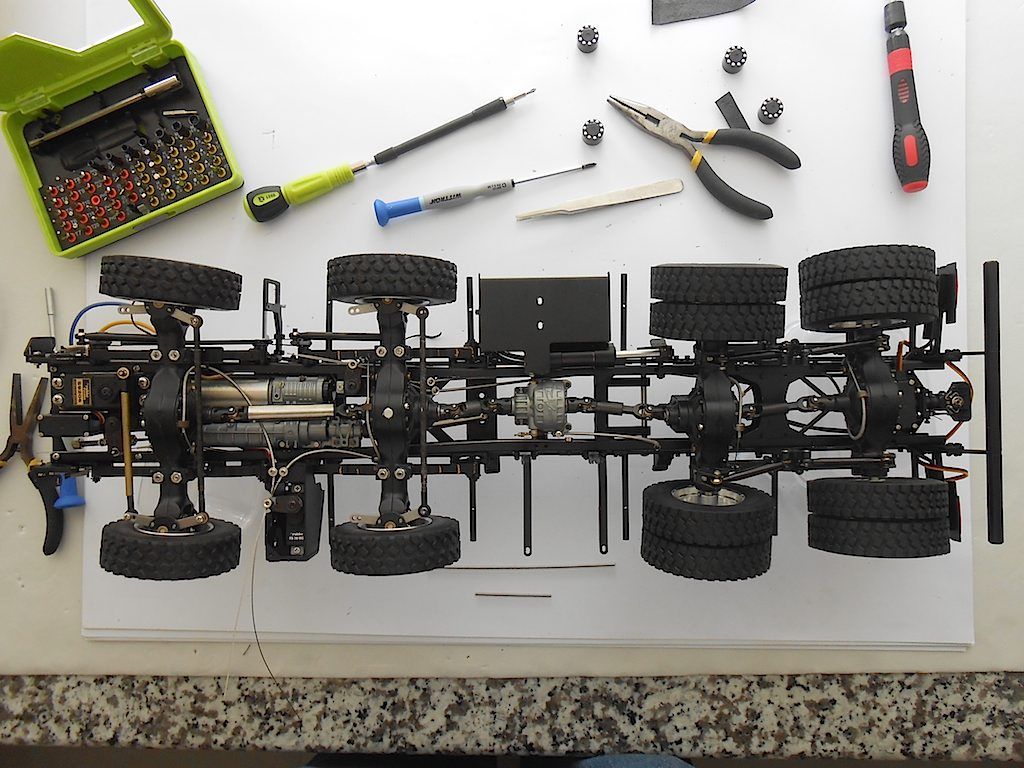 On a side note ... when I installed the motor/gearbox I left the cables from the servos dangling where they were ... not a smart move. Took some fiddling to get them where they belonged. 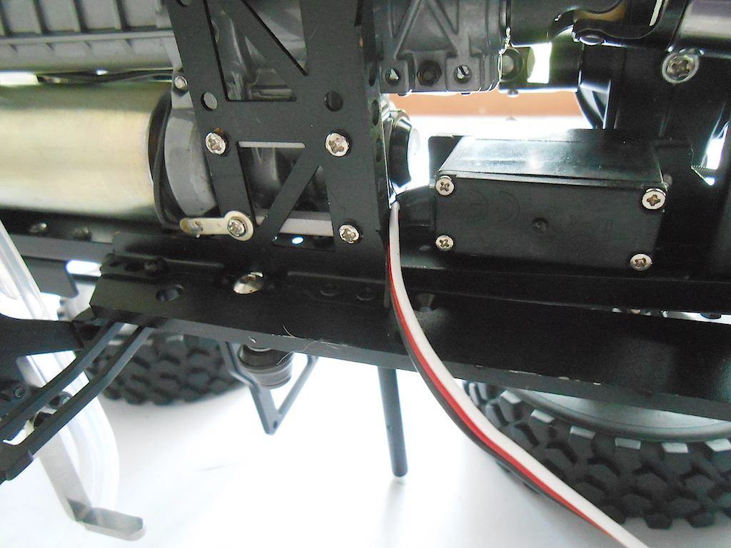 Well, now is the time to get out the remote control and start fine tuning the servos and checking gearshift and steering before I start on the driver's cabin etc.
__________________
Cheers, Stephan (Rakthi is the one in the avatar) Last edited by Rakthi; 06-22-2015 at 01:27 AM. |
|
#3
|
||||
|
||||
|
Spend time sorting out the settings. Lucky the RC is pre-programmed by ScaleART for their models. Saves a lot of time. Just pick the variation you want and you got the basic settings.
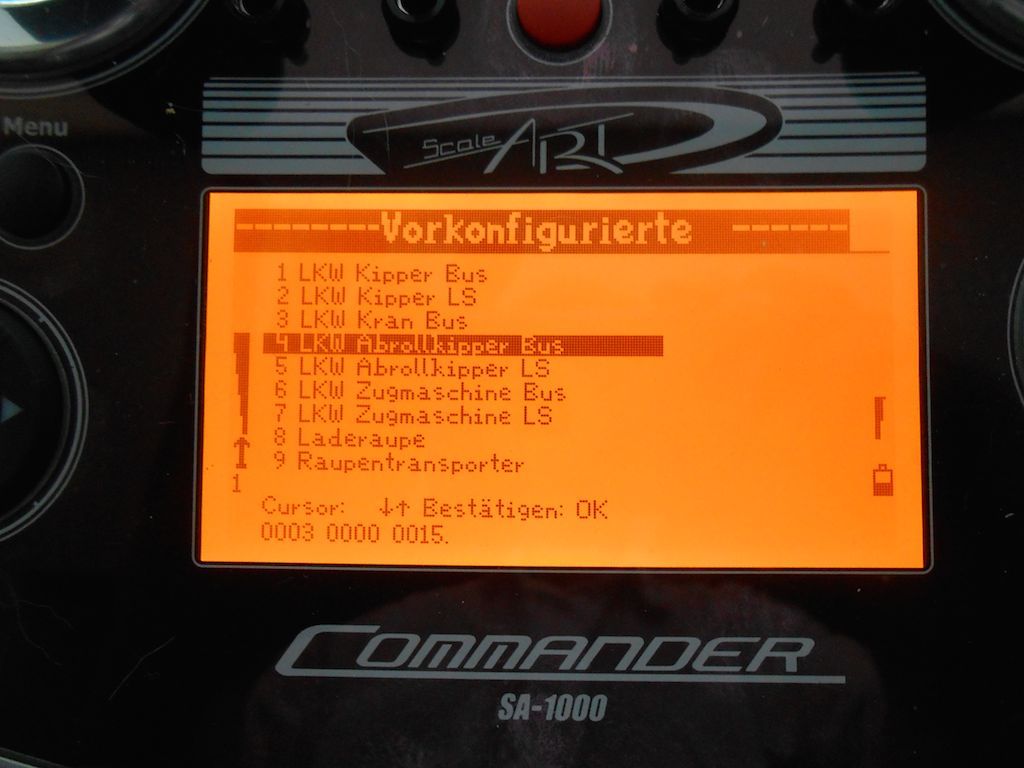 Of course they still need a bit of fine tuning. 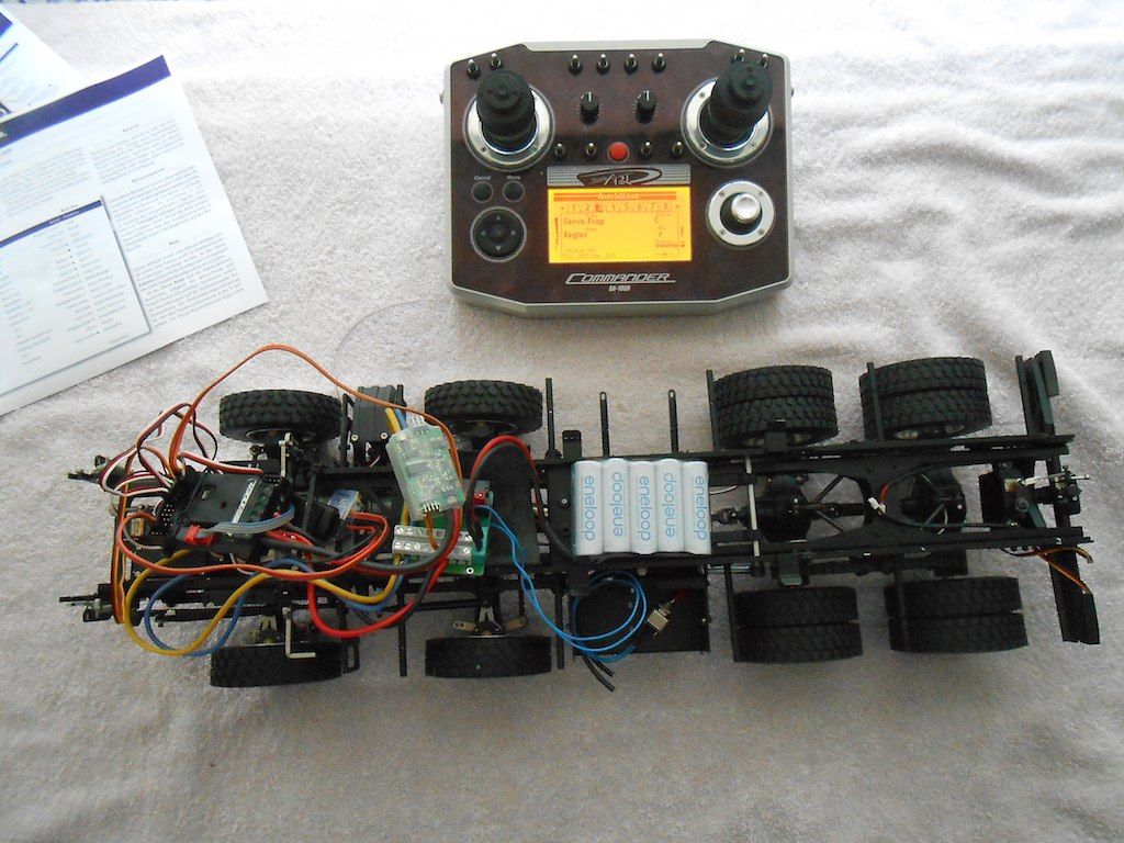 Had a bit of a problem with the ESC ... took me a while to figure out how to do it. First spend time looking for the jumper before I realised it was already on the ESC although on the wrong pins. Then couldn't get the jumper off the pins so I could move them to the program pins to "marry" the ESC to the Sender. Had to cut the heat shrink off. Also having the instructions in technical German was a tad confusing .. 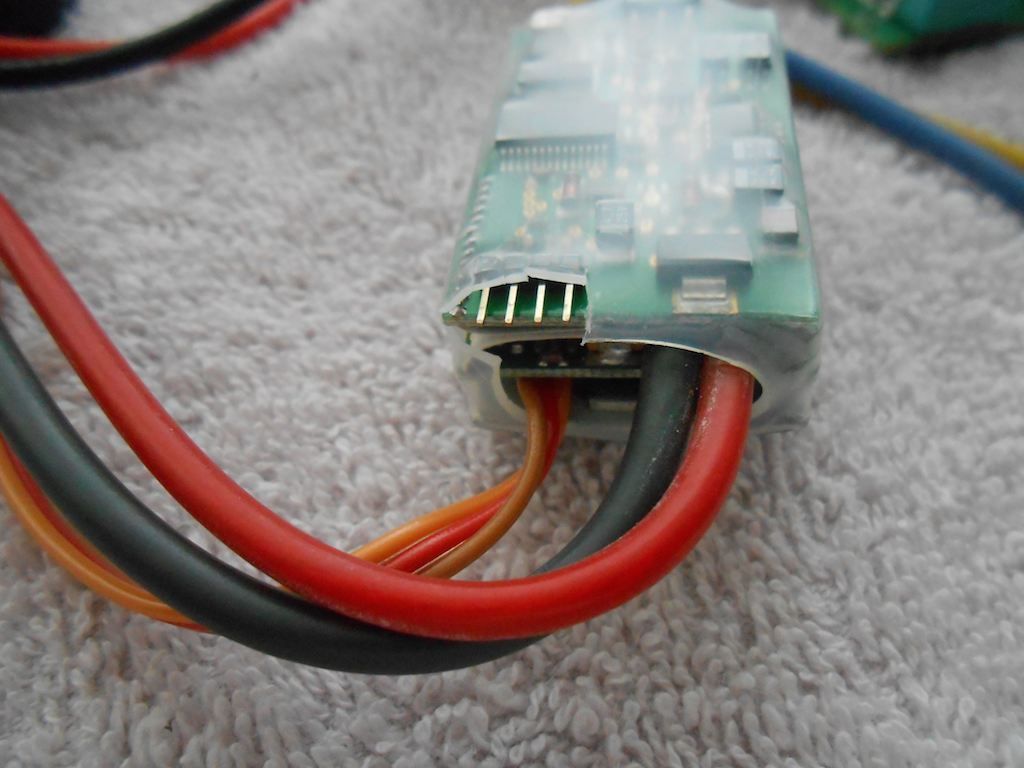 Well got it all sorted Just one little problem ... mixed up the plug position from the trailer coupling servos with that of the gearbox servo and succeeded in burning out the one from the gearshift ... Lucky the one from the trailer coupling in the back is the same. So guess I will have a manual trailer coupling until the new servo I ordered arrives. Meanwhile the truck has moved under its own power. Now just sort out some little niggles in the servo settings. Like why the front diff lock servo locks the diff when I turn on the power etc.
__________________
Cheers, Stephan (Rakthi is the one in the avatar) |
|
#4
|
||||
|
||||
|
I was lucky that to replace the fried servo I did not need to take the whole contraption out of the frame. Was a bit tight, but succeeded in doing it without major surgery. Before I replaced the burned on with the one from the trailer coupling, I followed Propshafts method of cutting off a bit of the rubber around the wires. Made it much easier to get the screw in, and as an added bonus I can now get the wire away from the servo horn of the centre diff. (So thank you Propshaft!)
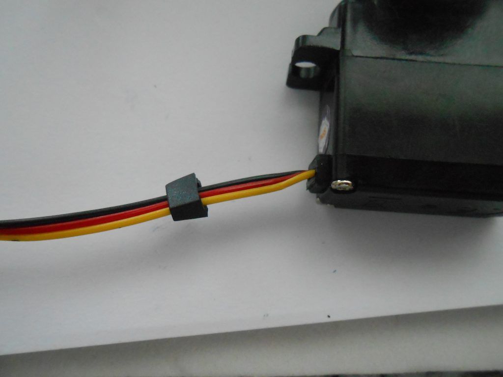 Just look at the difference. 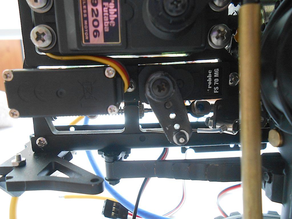  So that's one very burned servo ... 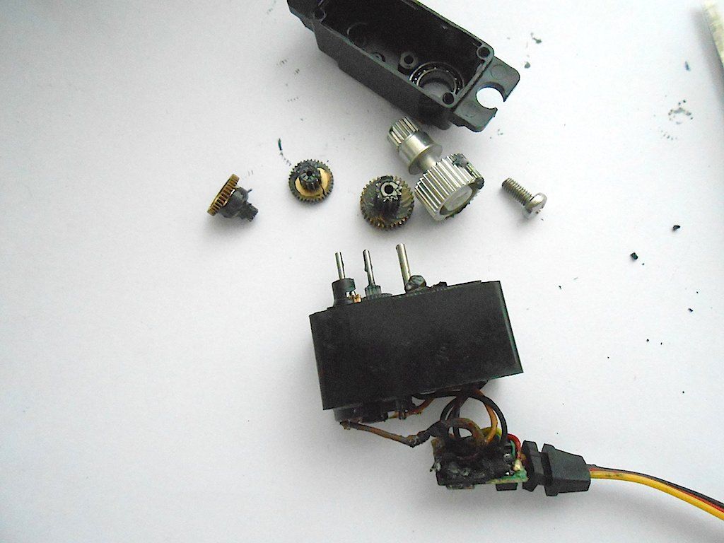 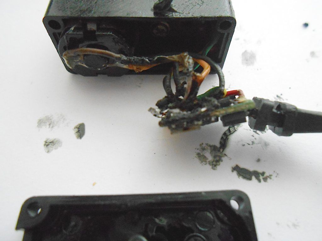 All because firstly, I was so stupid not to label the plugs correctly, and secondly I didn't check the numbers on the slots small as they might be ... Lesson learned. 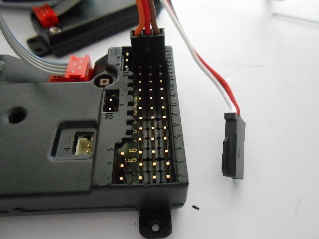 Guess the servo burned out because the trailer coupling was set for the full 100% sweep, thus keeping the servo trying to reach its endpoint. All that is sorted now. Made easy peasy with the Commander Sender. Here adjusting the rear diff lock servo. Only needs about 50% of it's travel to be locked. 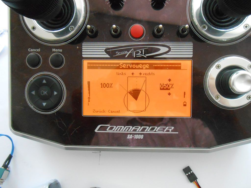 And the problem with the servos of the centre and front was just reversing the directions of operation. 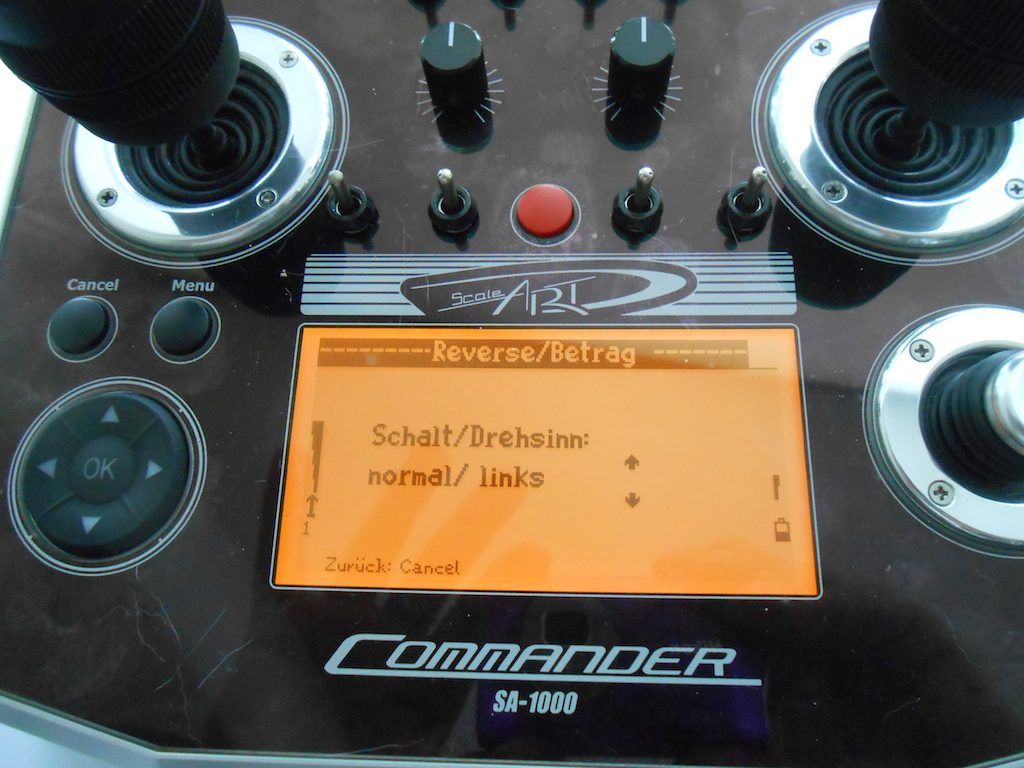 So all servos now have their limit of travel set, so no more buzzing or juddering anymore. Then check the tension on the pull cables and trim them to size. Adding a bit of crazy glue at the ends so they don't fray. 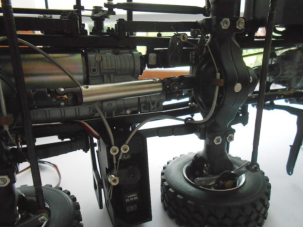 The liquid electrical tape I ordered arrived yesterday. Going to use that to on the LED board of the rear lights instead of the home made piece of rubber. 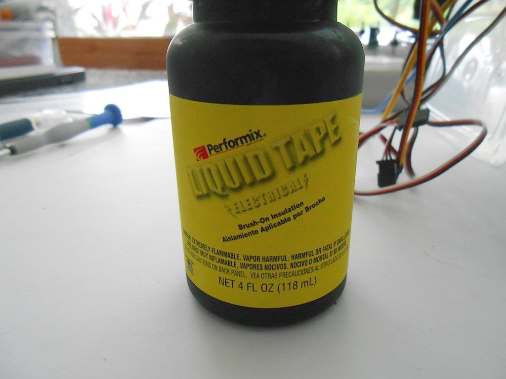
__________________
Cheers, Stephan (Rakthi is the one in the avatar) Last edited by Rakthi; 06-24-2015 at 12:30 AM. |
|
#5
|
||||
|
||||
|
Looking great. Glad my little trick could help.
|
|
#6
|
||||
|
||||
|
Yup Propshaft, one of those things I would never have thought about.
 Started on the driver's cabine. Part 1 of this group. Before screwing things together "dry fitted" some parts and noticed that the white from the cabin shows through the "teeth" at the front. 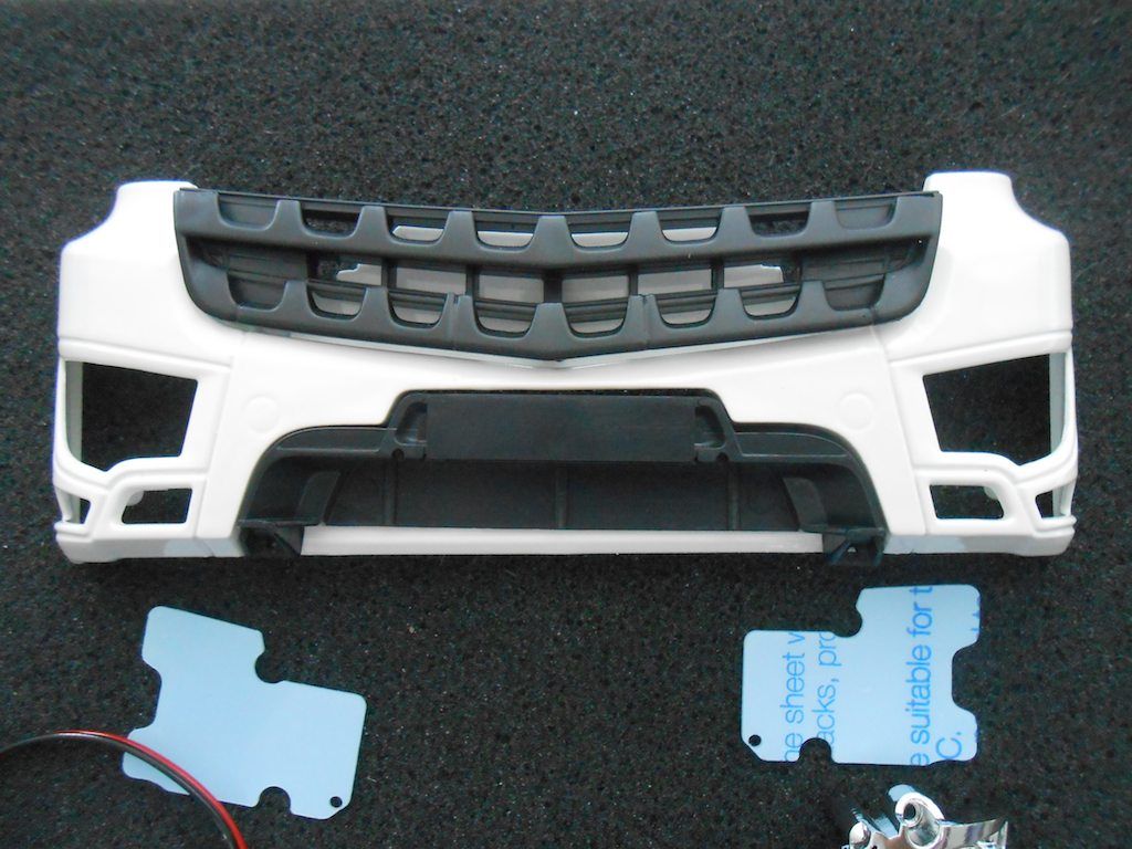 So decided to do something about that and paint that bit black (I could have used tape like Christian - aka Newcomer_2 but not to be found here on this island). Here I had another senior moments and first time around I painted the bottom part which doesn't need it. Good thing one can's see that bit once everything that needs bolting on is bolted on. 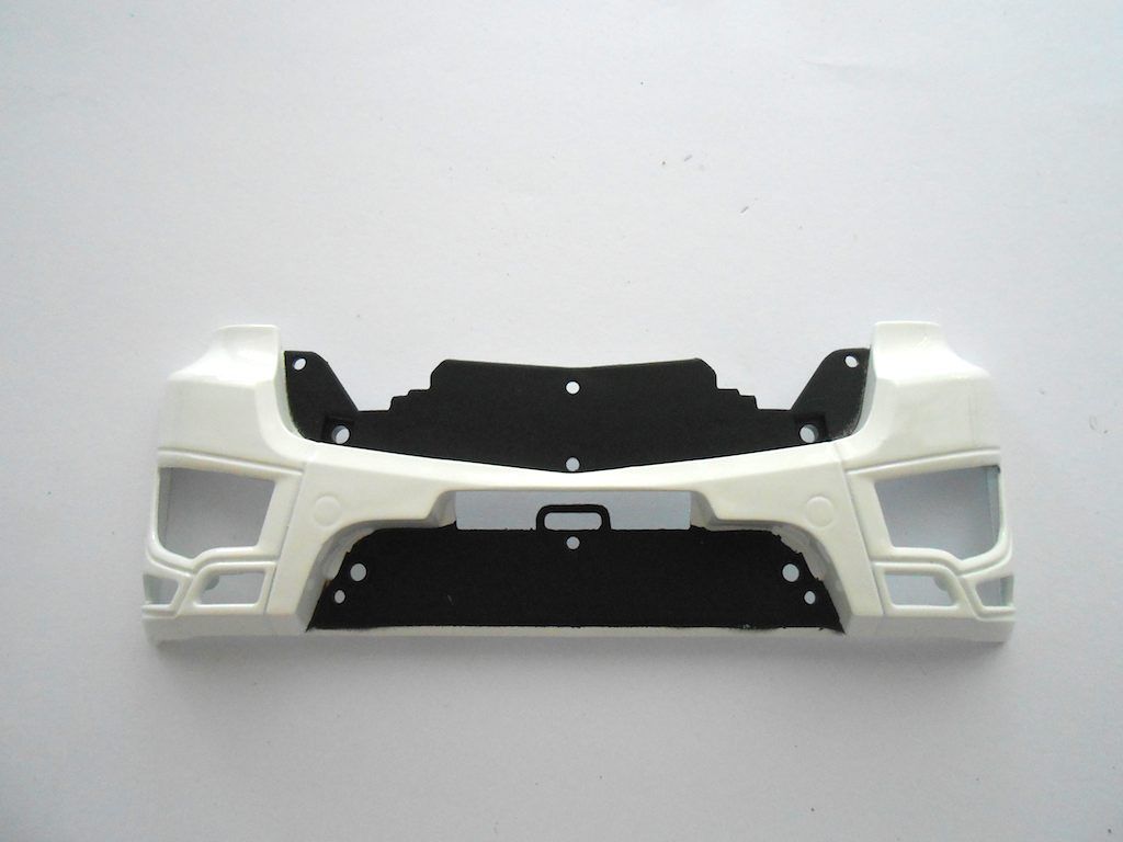 Here the first step of this group. (getting that blue plastic film of the plastic was about the most difficult and tedious thing of this part of the build) I got a bit of black speckles from the spray paint on the back. No biggie as the back of this part will not be visible. 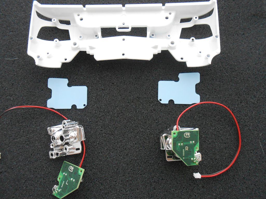 The plastic and the little black cover are put in place. The headlight will bend the plastic in place. A bit tricky to do. The little hole in the plastic is in case one wants to install the headlight protection grid. The bolt for that needs to go in that place. 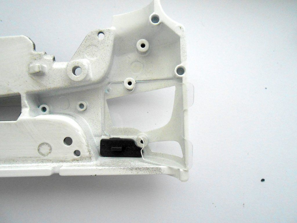 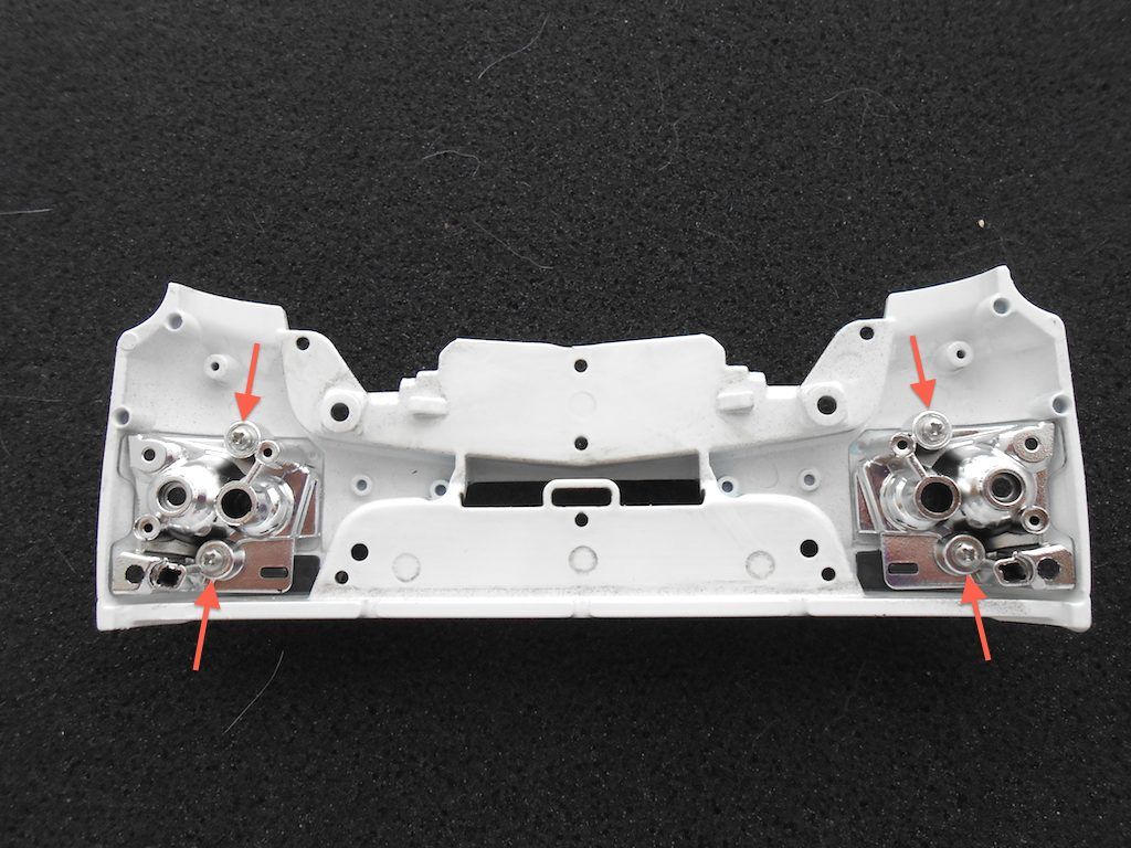 Next up the LED boards which are held in place by the steps. (in photo supposed to be 3 self tapping screws instead of 2) 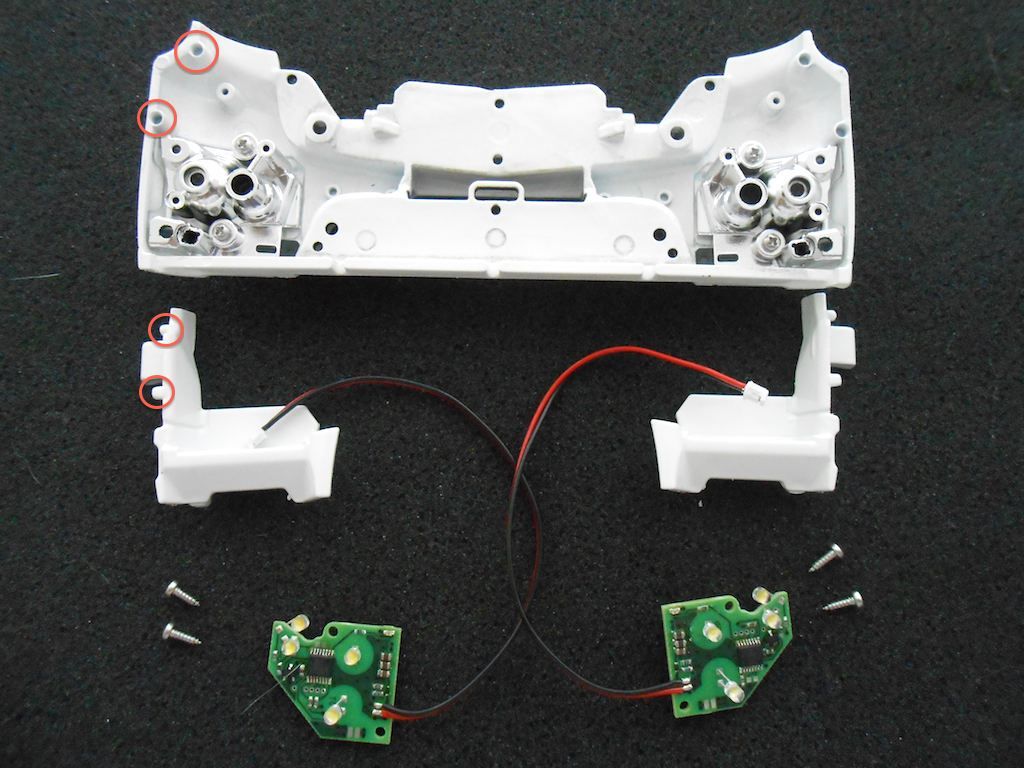 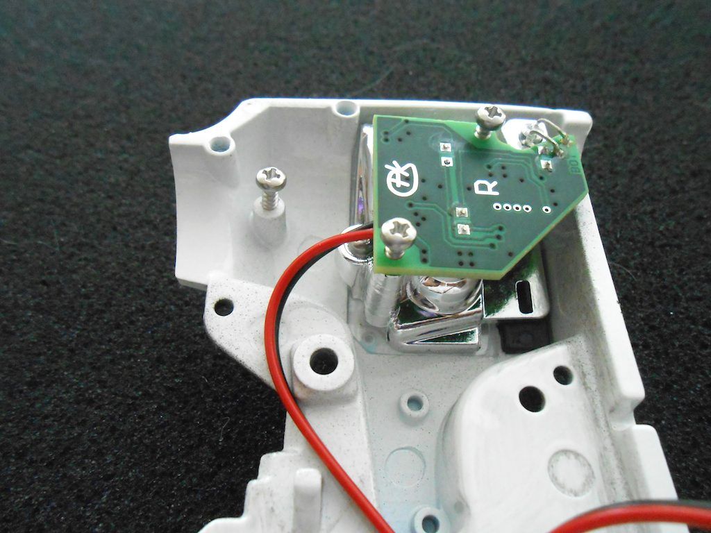 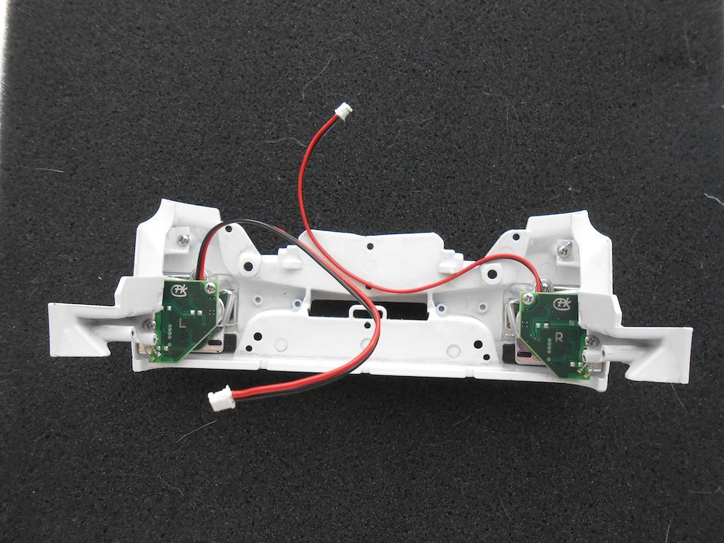 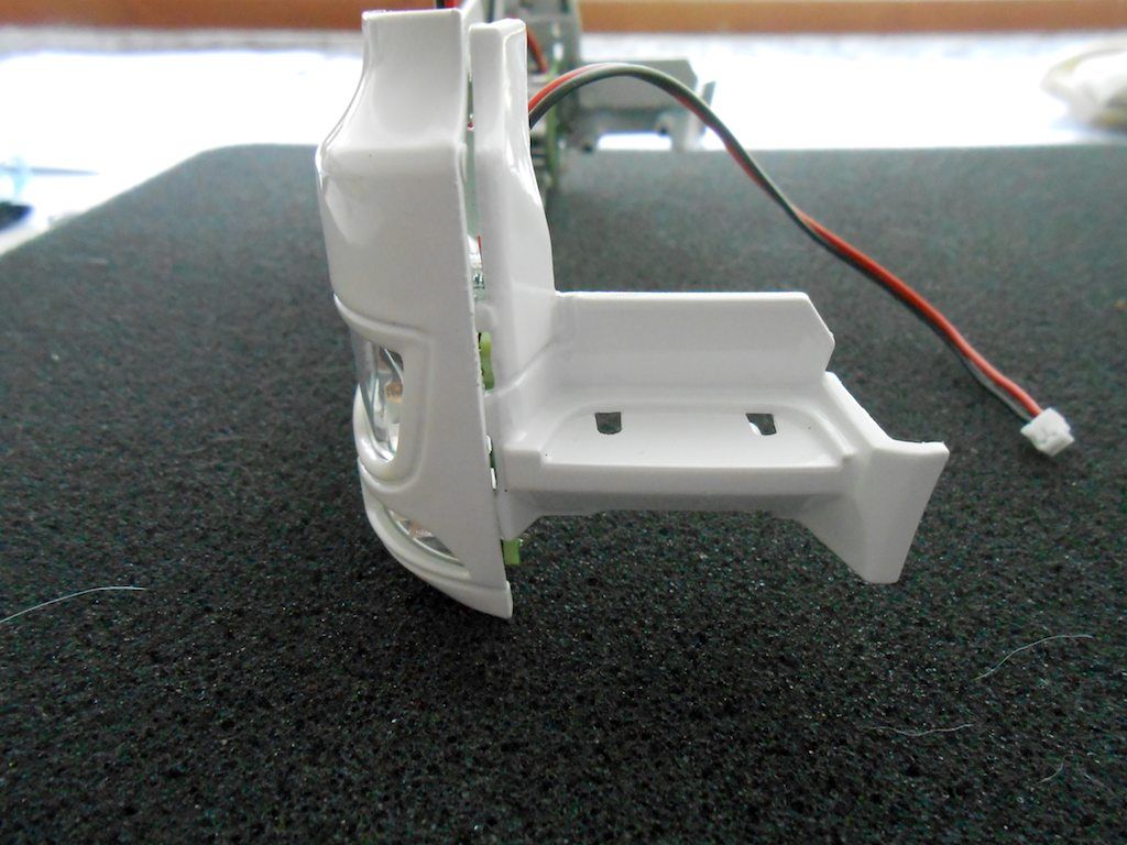 Tread "rubber" glued in place. Manual says to use 2 component stuff, but used crazy glue. 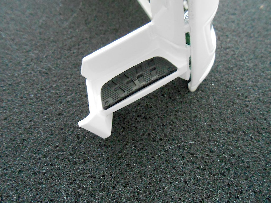 Now the lower step and the metal bits that are part of the upgrade for the AROCS Cab. Needed because otherwise too easy to bend/loose the lower step if one goes off-road with the truck. 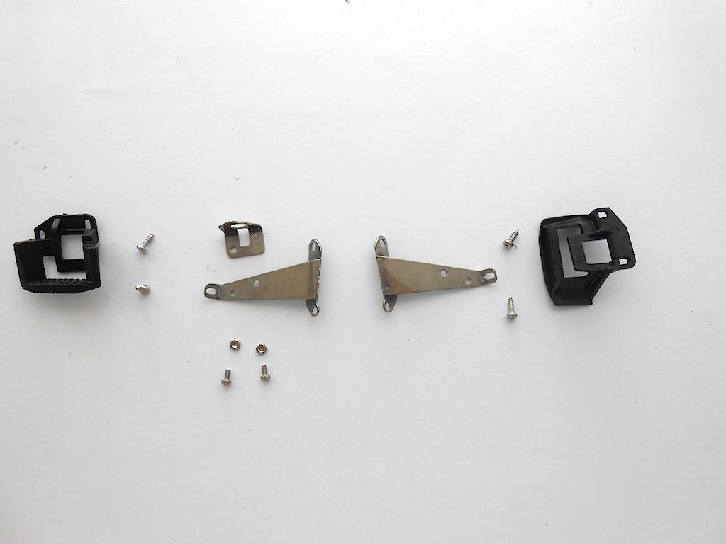 Here one can attach the on/off switch. the 2 openings are to line up with the bigger holes and is where this assembly bolts to the chassis. 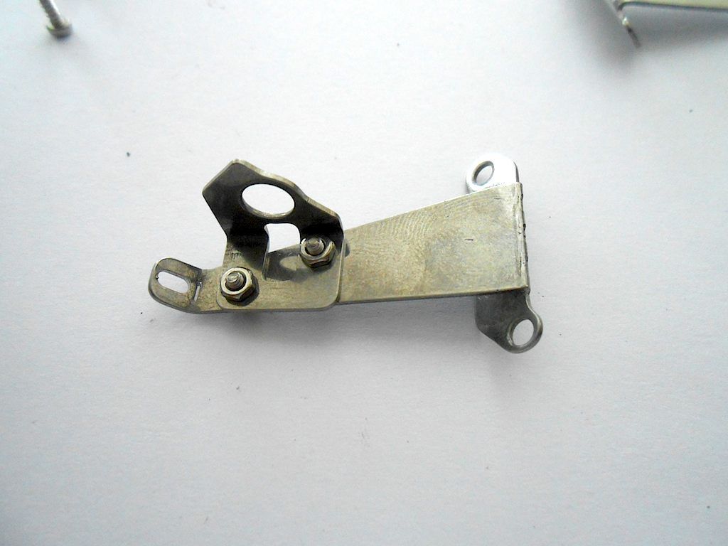 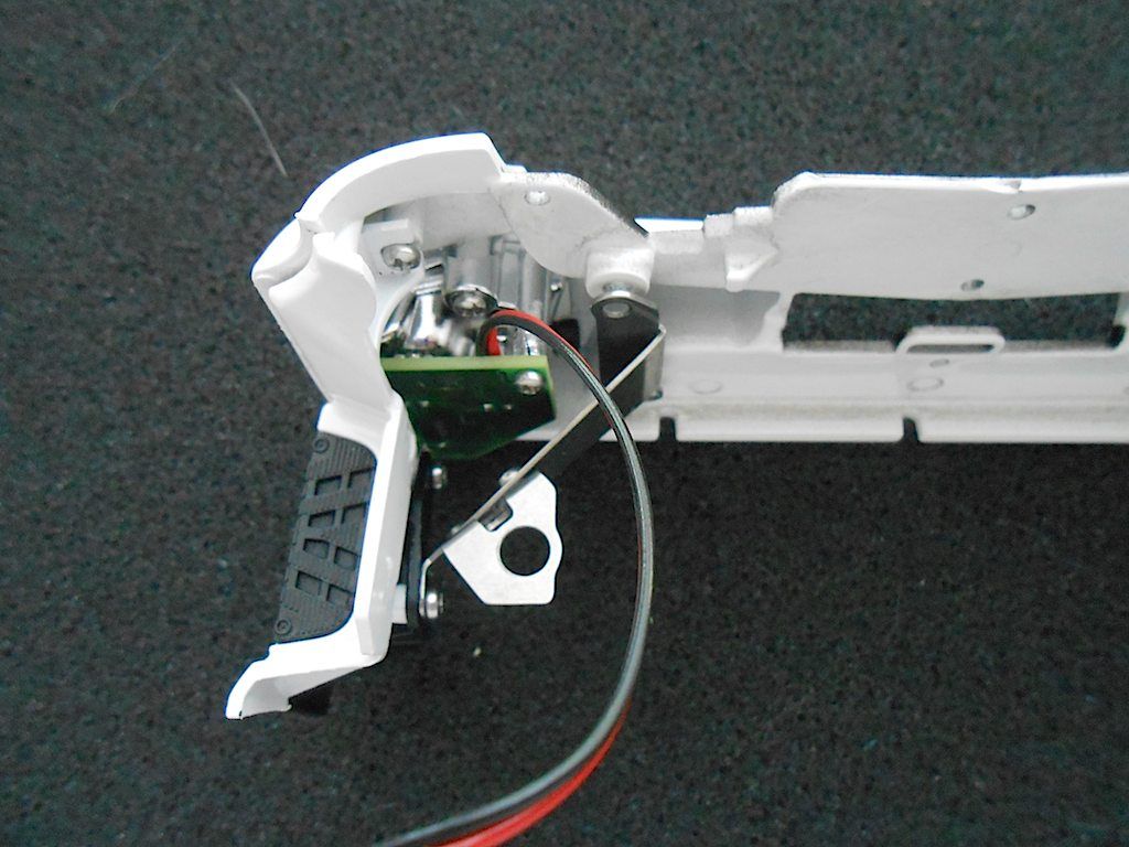 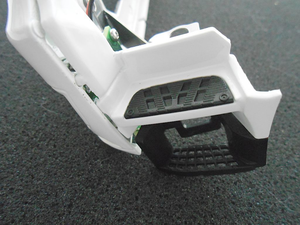
__________________
Cheers, Stephan (Rakthi is the one in the avatar) |
|
#7
|
||||
|
||||
|
Part 2
Finishing off the front of the bumper. The square nuts are where the bolts go that attach this part to the chassis. There is an indent in which they fit very tightly. 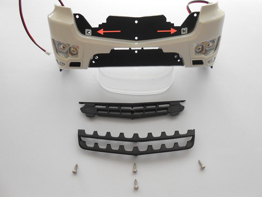 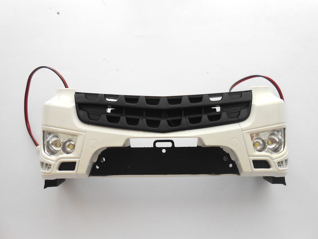 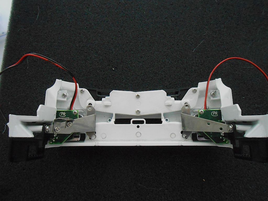 Bottom part of the bumper. Same as above. The square nuts from the bolts holding this assembly to the chassis fit in an indent. 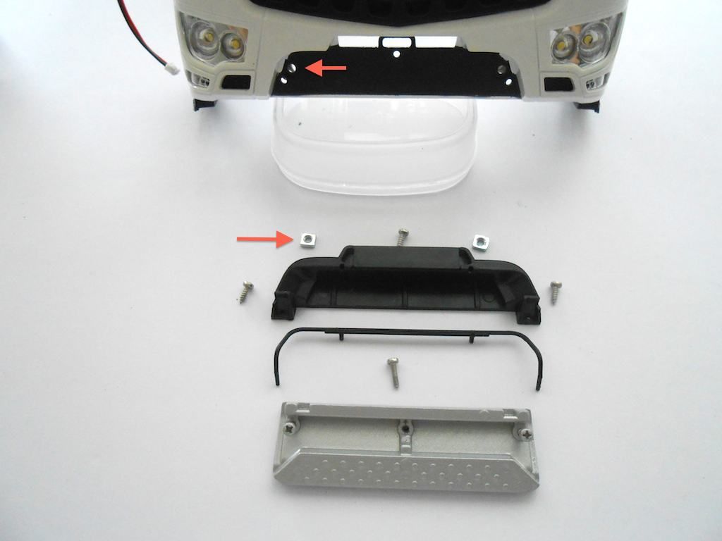 The thin bar gets glued with four drops of glue in the small openings provided. 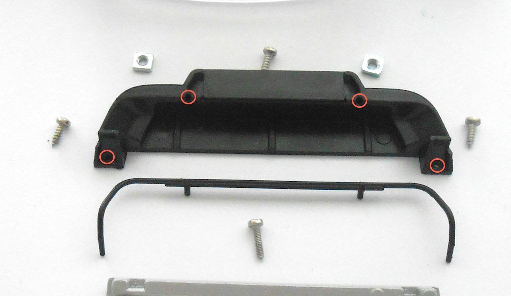 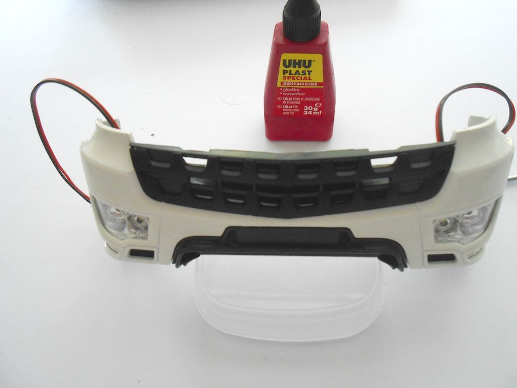 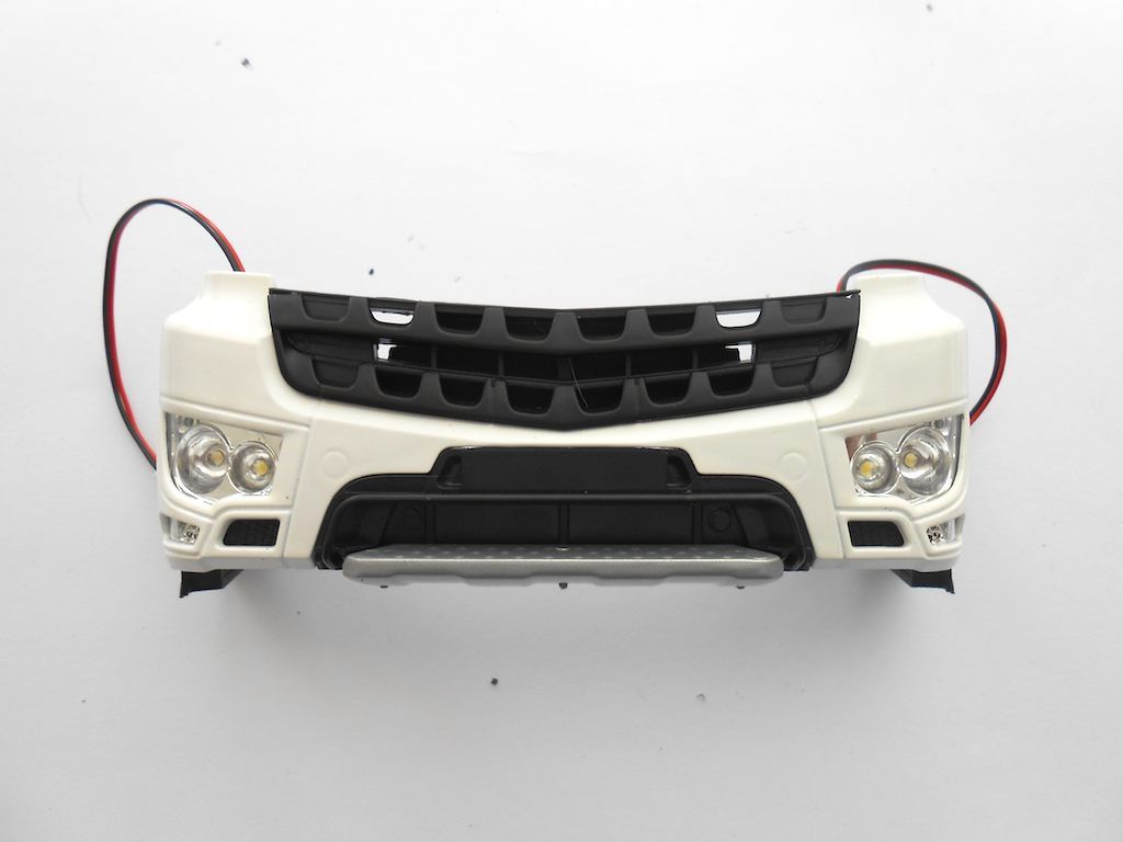 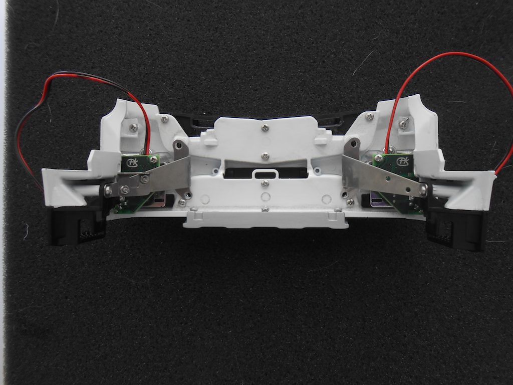 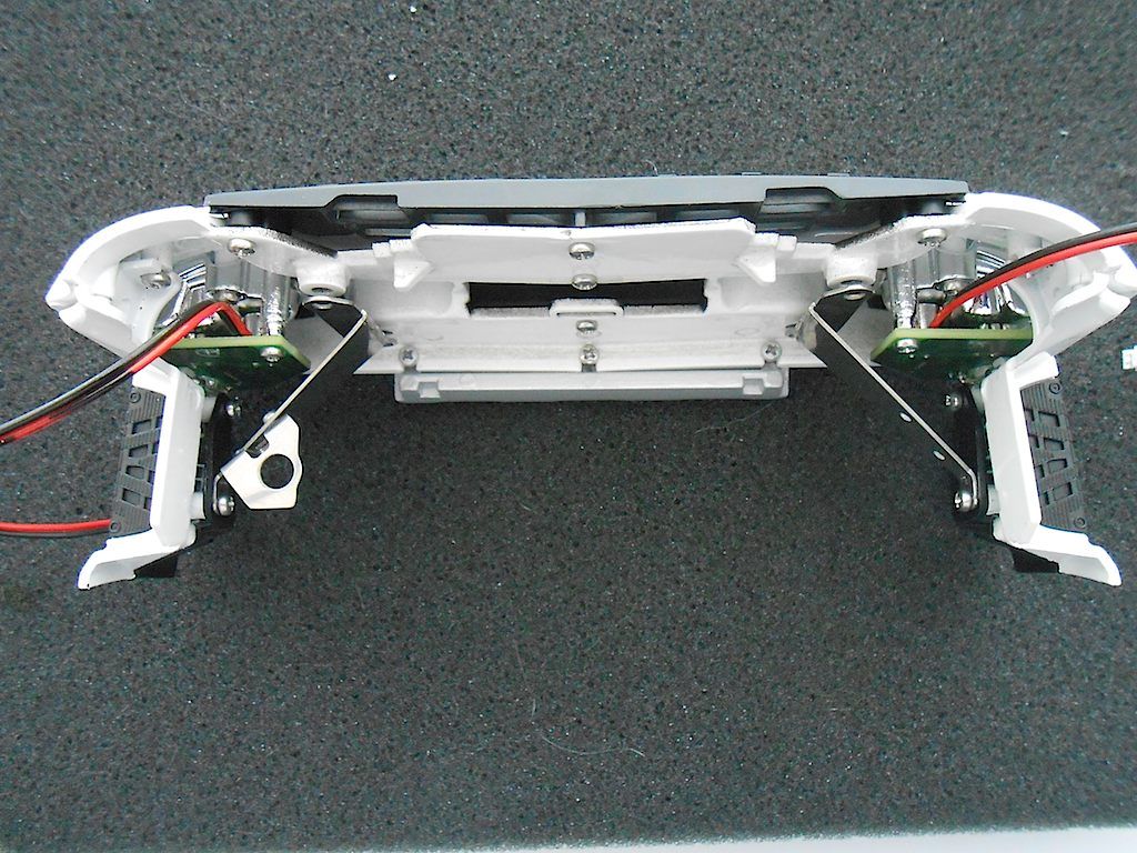 Next part should be the doors if I follow the manual.
__________________
Cheers, Stephan (Rakthi is the one in the avatar) |
 |
| Tags |
| 8x8, arocs, scaleart |
| Currently Active Users Viewing This Thread: 7 (0 members and 7 guests) | |
|
|