|
|||||||
| Highway Trucks and Trailers On road trucks and trailers single and twin axle trucks. |
 |
|
|
Thread Tools | Display Modes |
|
|
|
#1
 09-11-2021, 01:32 PM
|
|||
|
|||
|
Quote:

|
|
#2
09-11-2021, 01:46 PM
|
|||
|
|||
|
Bruder Piggyback Forklift Build part 10
I'm going to split the installation of all the electronics into two parts. In this post I'll show all the components I used and some modifications. In the next I'll go over the actual installation.. At the end of the last post I mentioned that I hooked everything up and tested to make sure that after all the putting together and taking apart that it would all work properly. This photo shows everything laid out on a table and temporarily wired up as I tested. [img] 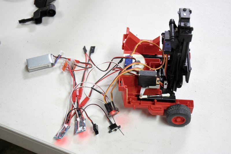 [/img] [/img]Man, what a mess of spaghetti. In this photo you see the following parts: 1 battery pack, 2 ESCs, 1 6-channel receiver, 4 JST connectors, and next to the battery pack a pair of 3 terminal WAGO connectors. Will it all fit? This is the battery I ultimately ended up using. While 500mAh doesn't sound like much capacity I have found in use that I can easily get a good solid hour of continuous run time out of it. And it fits easily into the space available. I purchased this particular battery from https://www.buddyrc.com They are an online only RC hobby store located in Columbus, OH. They primarily deal with the airplane/drone crowd but what hobby store doesn't. BTW, if you are looking for a RadioMaster transmitter they are dealers and also carry a wide array of spare parts. [img]  [/img] [/img]This is the receiver I used in this build. It is a 6-channel DSM compatible unit so it will work with almost any Spektrum radio as well as Open TX radios such as the RadioMaster. This receiver is the smallest 6-channel one that I know of that will take standard servo connectors. The only ones smaller use soldered connections instead of plugs. These receivers also have the advantage of being relatively inexpensive. This one is a bare bones model by which I mean it doesn't have telemetering or a diverity or duplex antenna. I purchased this from BuddyRC also. Be aware if you shop for one of these they come in two basic versions. The one shown is the 'top' connected version. They also make it in an 'end' connected version which is going to be about 1/4" longer and you would also need extra room at the end for the plugs. [img]  [/img] [/img]This next photo shows one of the ESCs I ended up using. These are 2S, 10A rated units. They have a 1A BEC and no braking. I originally wanted to go with 3S ESCs but couldn't find any that worked properly or that didn't let the magic smoke out after a few seconds. I really wish there was a source of US made ESCs. These were obtained on Ebay. They are all made in China so I don't think it really matters much which vendor you pick, I'd just look for one who states they ship from within the US. On the right side you can see a large capacitor extending out from the circuit board. This is apparently a new design, and so far, mine have worked well. [img] 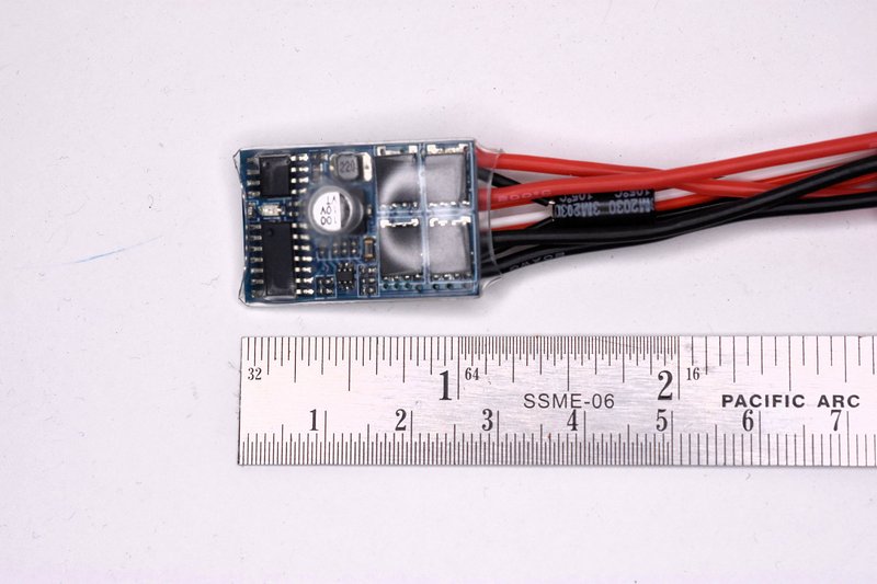 [/img] [/img]I made a few modifications to these ESCs. They came with a switch attached to wire leads to turn the ESC on and off. Since I was going to use a master switch I didn't need the attached switches. And I especially didn't need two switches. To remove the switches I had to remove the plastic heat shrink that had been put on by the factory. Just use a sharp knife and pare down along one edge of the circuit board and peel off. [img]  [/img] [/img]Then using a small soldering iron I heated up each blob of solder on the circuit board at each switch wire location on the lower right as shown. When each blob melts just pull the wire free. Don't remove the little blobs of solder. [img]  [/img] [/img]Without the switch there is no way to turn the ESC on. Simple fix, just solder a small jumper across the two pads where the switch wires used to be. I just used a small piece of wire snipped from a resistor. The blobs of solder left behind from removing the switch wires should be enough. [img] 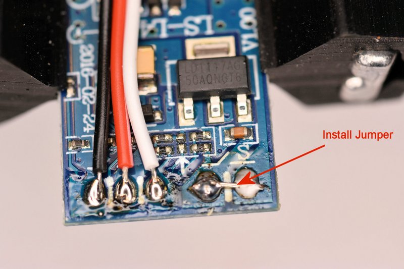 [/img] [/img]These ESCs are going to be mounted in a plastic body and all the wires on and around them will be insulated. But I still felt it wouldn't hurt any to re-insulate the boards. You could put heat shrink back on like they had originally but I decided to wrap them in Kapton tape. Kapton tape is very thin, very strong and has a very high dielectric or insulting rating. It's also not cheap. But I had a lot left lying around from my early 3D printing days when we used to put Kapton on the build platforms as a surface for the print to stick to. I primarily used it because it was a lot thinner than the heat shrink and I wanted all the spare room I could get. [img]  [/img] [/img]Since I had two ESCs that were going to be connected to the same receiver the last modification was to remove the red + wire from one of the servos so the receiver would only get power from one ESC. So, next post I'll finally get to what most of you have been wanting to see. How I put it all the electronics inside the body of the fork lift.
|
|
#3
09-12-2021, 01:07 PM
|
|||
|
|||
|
Bruder Piggyback Forklift Build part 11
OK, time to finish this up. Will everything fit inside. Of course, didn't you see my first post? There was some trial and error involved in deciding where to put the components but it actually was easier than I was afraid it would be when I started this conversion. There were a few snags and I'll point them out so you can avoid them. The first step was to lay in a length of two conductor cable for the battery power supply as shown. It has a JST connector on one end and is longer than anticipated and will be cut to final length later. The red wire will go to the master switch under the operators seat and the black wire will actually get pulled back about to the center of the wheel housing for the negative return to the battery. [img] 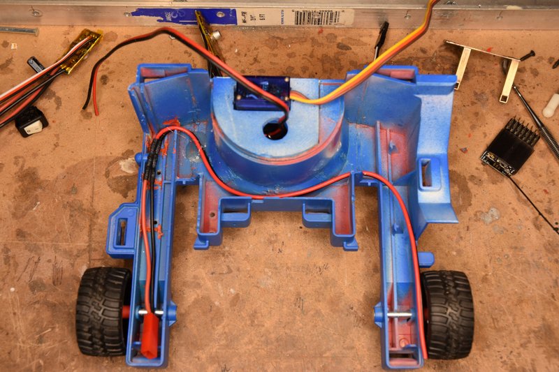 [/img] [/img]The first component I mounted was the ESC for the drive motor. I simply hot glued the ESC to the back right side of the rear wheel housing as shown below. The large capacitor on top was just pushed over so it laid on top of the wheel housing. [img] 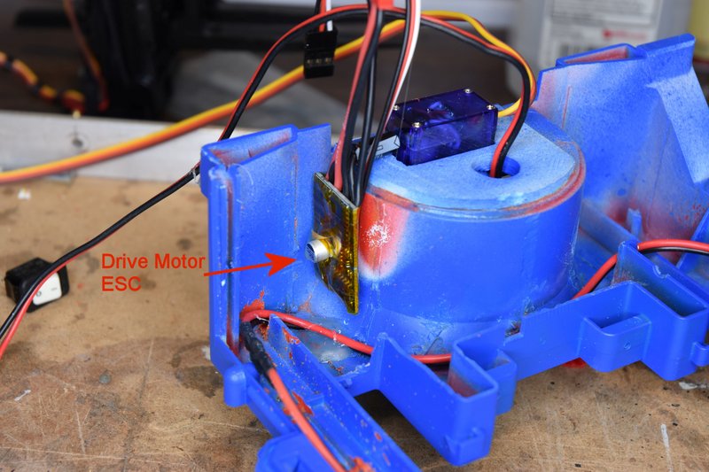 [/img] [/img]So logically the second ESC for the lift motor should go on the other side of the wheel housing. So that's where I mounted it and again bent the capacitor over to lay on the wheel housing. [img] 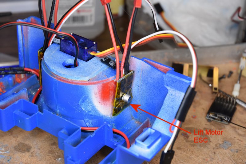 [/img] [/img]Using a piece of servo tape I mounted the receiver in the position shown. I placed the terminals for the servos on top so they would be easy to get to and figured that would give me room underneath to coil up excess servo lead. I bent the antenna wire to run along the side of the left wheel arm and taped it in position. [img] 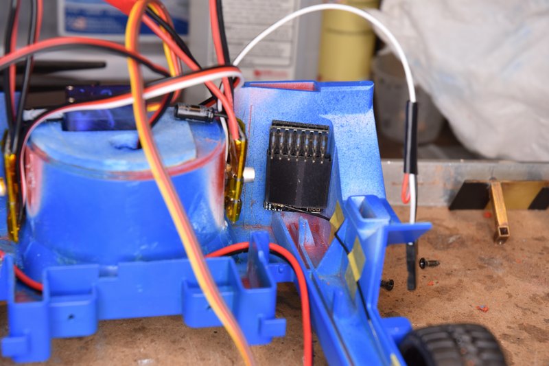 [/img] [/img]SNAG #1 - If you have been following this build and seen the 3D printed parts I've used from Thingiverse, have you wondered why the steering servo mount is straight instead of curved on the left side? It' because part of the top body section hangs down over the left side of the wheel housing in this area and there isn't enough clearance for the printed part. I tried assembling the top and bottom body sections together at this time to check fits and clearances and found that the capacitor on the lift motor ESC would not fit. If fact none of the wires sticking up from the ESC would fit. I think I got so used to just working on the lower body section that I forgot about this clearance issue. So after some study I removed the ESC and remounted it to the position shown below. I also mounted it lower so the wires wouldn't get in a bind with the top part of the model and bent the capacitor leads down over the front of the circuit board. [img] 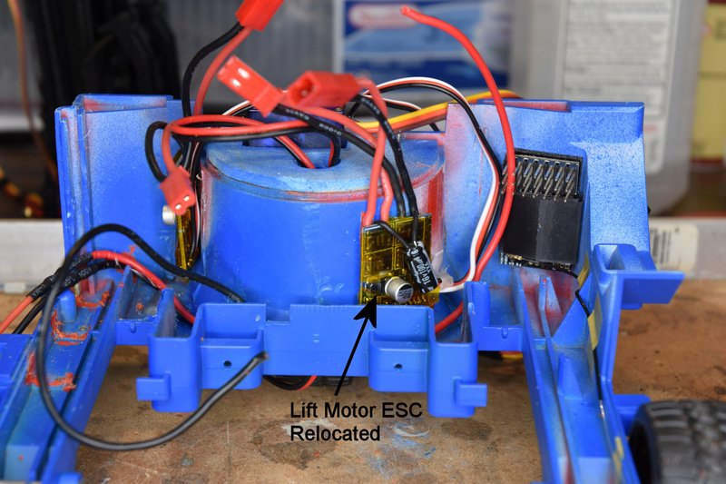 [/img] [/img]Next I mounted the master switch into the hole made previously in the top body section. In this photo I had placed the top body back into position to check clearance from the back of the switch to the receiver. Good reason for removing the drivers seat. [img] 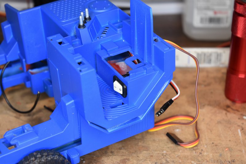 [/img] [/img]I wanted to be able to completely separate the top body from the bottom for maintenance and repair work if ever needed. So I installed a XT30 connector as you see. I used this connector because it was the smallest two conductor connector like this I had on hand. The JST connectors are longer when assembled and I though they might get in the way. While the XT30 works I now wish I had taken the time to find something smaller. This doesn't need to be a polarized connector either. The switch is just in series with the positive battery lead. You can also see the second red wire added to go from the switch back to about the center of the wheel housing. [img] 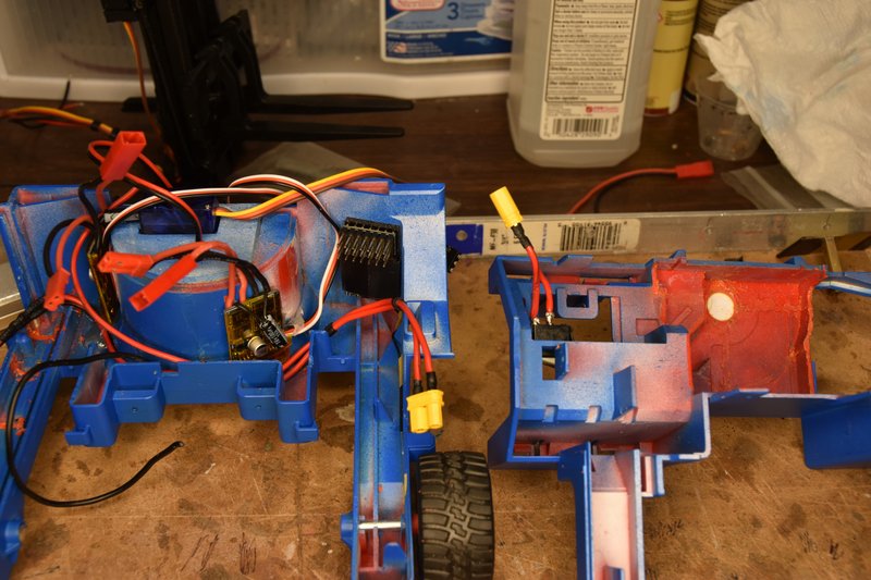 [/img] [/img]I had wanted to use the WAGO connectors to make the power connections. I really like those things but they were just a little too big to fit in the space between the front of the wheel housing and the front wall of the lift. I could have maybe put them at the bottom backside of the lift but would have then had to splice extra wire to the ESCs. Didn't feel like doing that much extra work. So I simply twisted the ends of the black wires and red wires together and soldered them. Then insulated the ends with a piece of heat shrink and a little tape. These wires are a little stiff so I held them in place with a couple dabs of hot glue. [img] 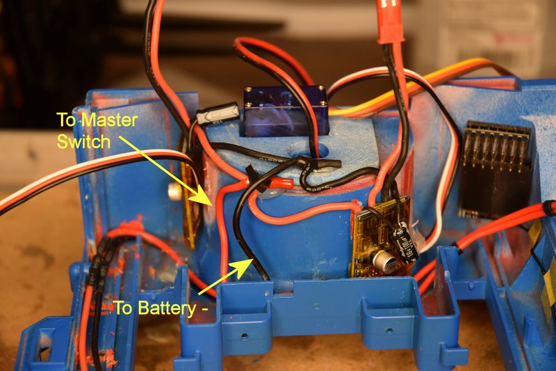 [/img] [/img]Reinstalled the mast platform retraction servo. [img] 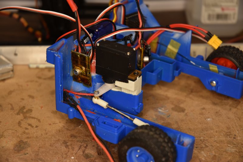 [/img] [/img]Followed by the battery platform. I covered the edges of the platform with a couple of layers to electrical tape to protect the wires from possible cutting. [img] 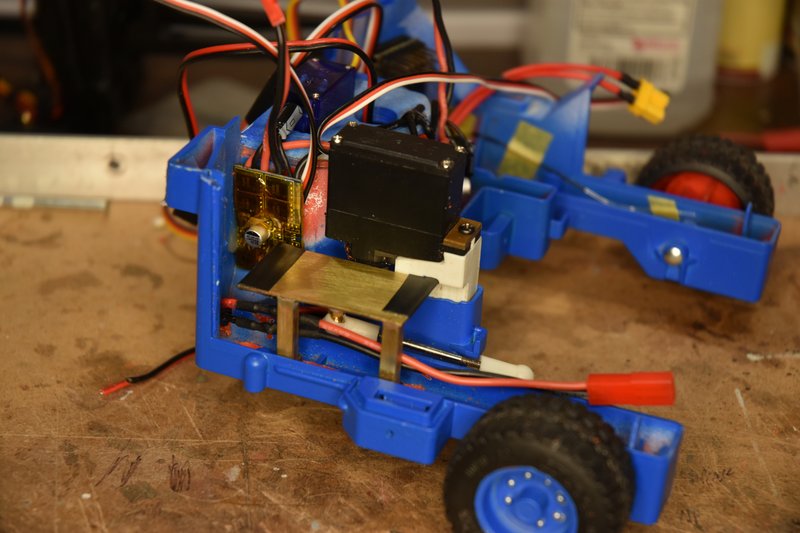 [/img] [/img]Next was to cut to length and splice the power leads from the drive motor to it's ESC. Solder and heat shrink tube to insulate. [img] 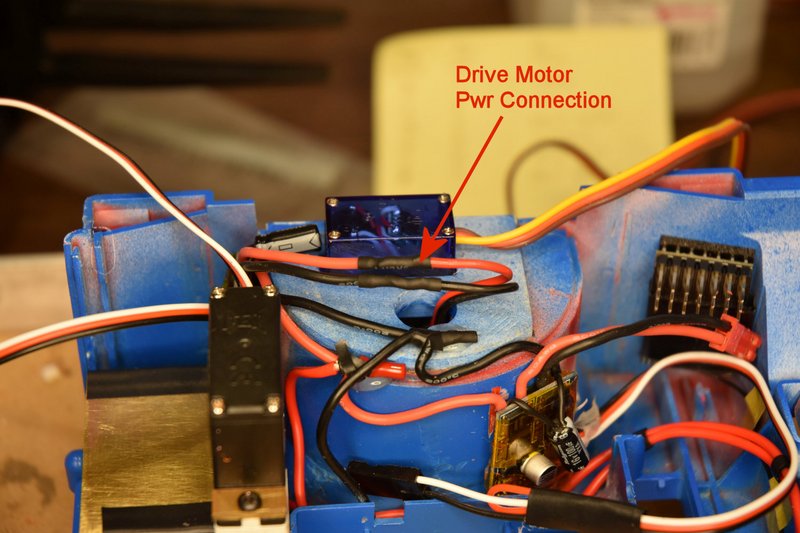 [/img] [/img]I then wrapped narrow pieces of tape around the tilt servo leads and lift motor wires on the mast assembly to bundle them together. Place the mast assembly back into place on the lower body and connect the servo linkage. [img] 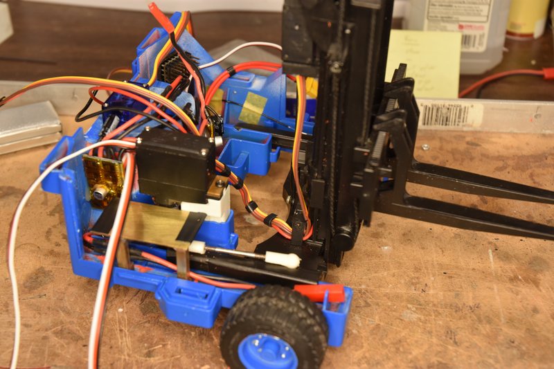 [/img] [/img]Then the lift motor leads and and ESC leads were trimmed to length, spliced and heat shrink. [img] 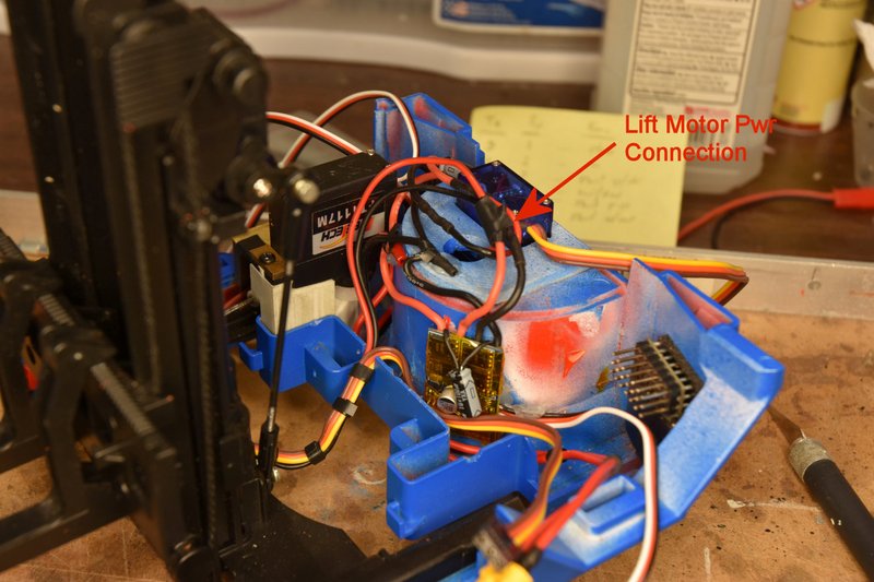 [/img] [/img]Next is to run the servo and ESC control cables to the receiver. I won't show all of these being run. I ran the cables from the drive ESC steering servo and mast retraction servo across the top of the wheel housing to the receiver. The lift motor ESC and tilt servo cables were run across on the bottom of the body to the receiver. Each cable needed to be shortened to some degree so I wouldn't have a huge mass of wires under the receiver. So I ran one cable at a time starting with which ever cable I had assigned to channel 6 on the receiver. And then channel 5 and so on. I'm not using channel 2 so it's open as well as the battery port since power is coming from the drive motor ESC. [img] 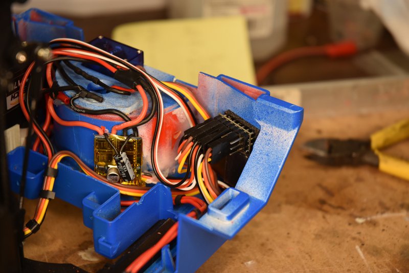 [/img] [/img]OK, as usual the web site is telling me I talk to much. Have to break this post here and will continue in the next.
|
|
#4
09-12-2021, 01:15 PM
|
|||
|
|||
|
Bruder Piggyback Forklift Build Part 11b
(continued from previous post) Ran the leads of the warning light on the ROPs through the notch cut earlier in the top part of the body and reinstall the ROPs. [img] 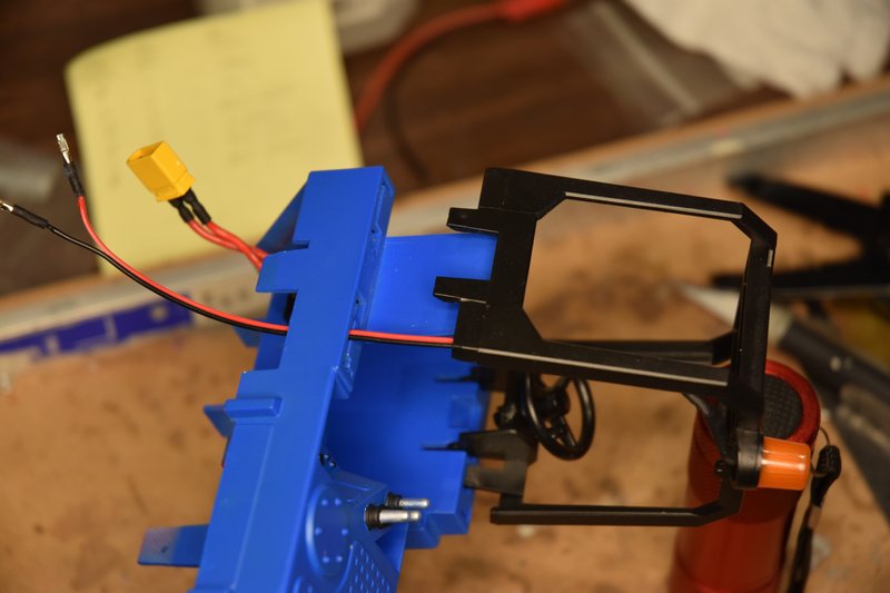 [/img] [/img]In this photo you can see how the leads to the warning light plug onto the positive and negative pins on the battery port of the receiver. This allows me to completely separate the top and bottom body parts if ever needed. [img] 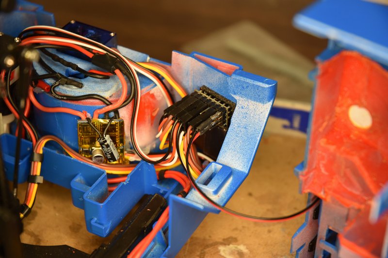 [/img] [/img]plug the switch leads back together. [img] 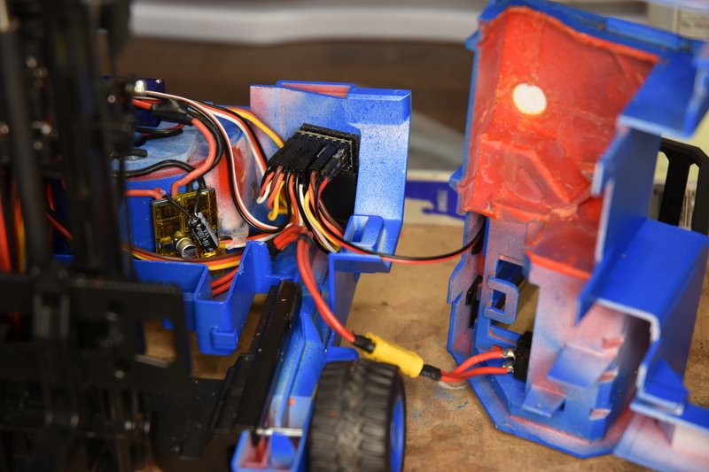 [/img] [/img]Install the battery and plug it in. [img] 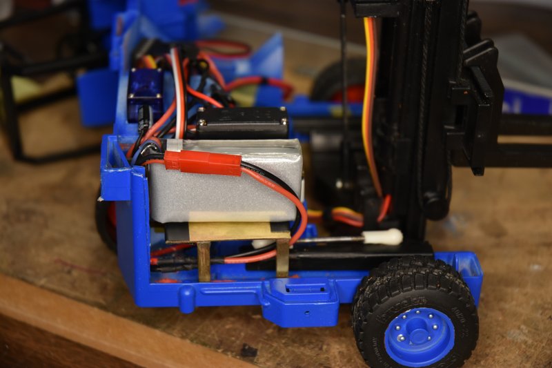 [/img] [/img]Turn on the transmitter and then flip the master switch and see if everything is going to function. Hooray, Success, let's button this thing up. SNAG #2 - I started to put the top body section in place and ran into a problem. The right hand side would go together just fine but something was keeping the left hand side from closing, not even close. A quick look down the hole under the drivers seat showed what the problem was. When I checked the clearance between the back of the switch and the receiver earlier the servo leads were not connected. I thought I had enough clearance but because of the size of the XT30 connector I was binding on those servo leads. What to do after I was so close to being done? After a little thought the fix was simple. Pried the receiver off the double sided servo tape and scrapped the tape off the inside of the body. Man that stuff sticks! I then turned the receiver 90 degrees counter-clockwise, moved it over towards the wheel housing and pushed it downward as much as it would go. plenty of clearance. And sorry, but I didn't think to take a photo at this time showing this but if you look at the photo above showing the receiver with everything plugged in and visualize it turned on it's side you'll get the idea. plenty of clearance for the switch connector now. Alright, put the top back in place, line it up and push it home and , wait, what??? Everything fits except the very back end won't quite go together. Oh for the love of.... SNAG #3 - Remember the clearance problem I talked about above that forced me to relocate one of the ESCs? Well turns out there's even less room between the top and bottom parts than I thought. I have 3 servo cables lying across that area and they are each only about 1.25mm thick. Apparently there is not even that much room as the cables were keeping the top slightly raised. I could have just squeezed the top and bottom together but I didn't want to put the wires under that kind of pressure. I could have rerun them around the front of the wheel housing but was concerned about generating noise by running more wires that close to an ESC. The fix is simple but frustrating. Very carefully thin the top and bottom body parts in the area where the clearance issue exists. The next two photos show the areas that are the problem and need to be thinned. [img] 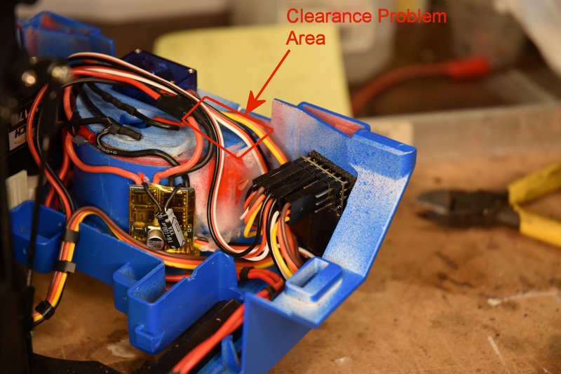 [/img] [/img][img] 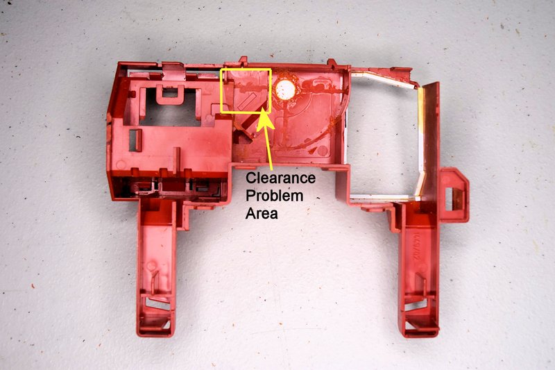 [/img] [/img]Pulling the servo cables off the receiver and moving them out of the way I started thinning by first using a motor-tool on the steering mount to bring the thickness on the left of the steering servo down to match the original body. This can be on a taper. Be careful not to grind the back edge of the part as that will show on the outside. Then using a flat riffler and sanding sticks I slowly thinned the top and bottom bodies in the areas shown above. Taking a little bit off, try the fit, take a little more, etc. until the top and bottom came together. I then rounded the sharp edges where the servo cables ran to minimize stress on them. Fortunately There was plenty of plastic left So I don't feel there is a breaking or cracking hazard. But be careful if using a motor-tool so you don't cut through the body. You only need about 1.5mm clearance in this area. If you build one of these fork lifts following my process, I would remove the material in this area back when I cut away all the other plastic that has to be removed. An easy way to measure the clearance would be to put a small ball of clay or similar material between the two halves before putting them together and then measuring the height of the squished ball. So, did it finally go together? Yes, hallelujah, success at last! One final step, install the operator's seat. [img] 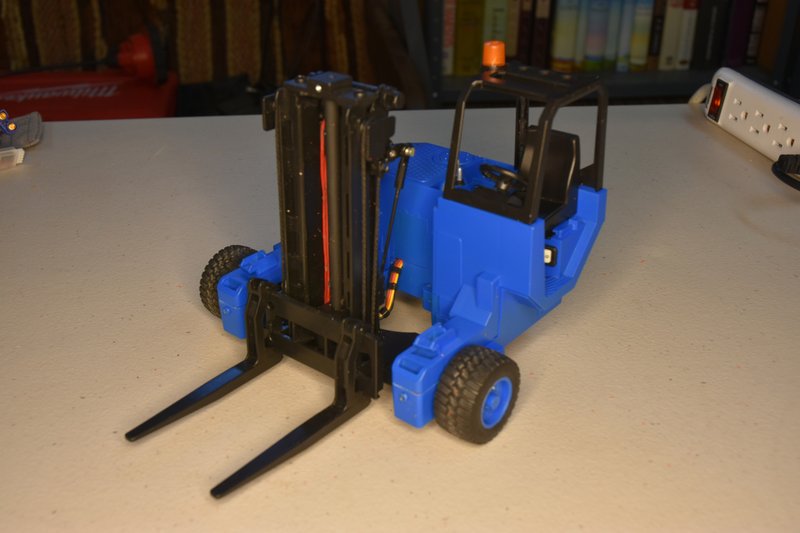 [/img] [/img]This was an incredibly fun conversion and I am very pleased with how it turned out. Took some experimenting, some designing, some fabrication and a lot of just looking and thinking. Everything I love about this hobby. If you decide you want to do one of these conversions please post up your results, especially if you do something different. Feel free to add it to this thread if you want. More than one way to skin a cat. Speaking of which, have you noticed how many different ways people have come up with to convert the Bruder D5? Now I've got to figure out how to modify the back of my flatbed trailer so I can haul this thing down the road.
|
|
| Currently Active Users Viewing This Thread: 1 (0 members and 1 guests) | |
|
|


 Hybrid Mode
