|
|||||||
| Highway Trucks and Trailers On road trucks and trailers single and twin axle trucks. |
 |
|
|
Thread Tools | Display Modes |
|
#21
 09-06-2021, 11:16 AM
|
|||
|
|||
|
Quote:
I love Adafruit, they are a great company to deal with. I use a lot of their components. I really like that they are in the US and manufacture a lot of what they sell in house. With the limit switches you just have to pay attention to polarity of diodes, as apparently I did not as noted in last post. For those not familiar with these limit circuits I should have mentioned also that these types of switches have both a Normal Open (NO) and a Normal Closed (NC) circuit which is usually shown on the side of the switch right above the pins. There are usually 3 pins or lugs for wiring, one is a common, one for the NO circuit and one for the NC circuit. For limiting motion of motor drives we want to use the NC circuit. On the switches I used that is the outside two pins. I cut away the third pin to avoid confusion later and a small diode will fit nicely into the space left. There are numerous utube videos detailing how to make these circuits and how they work. 
|
|
#22
09-06-2021, 01:49 PM
|
|||
|
|||
|
Bruder Piggyback Forklift Build part 6
Ok, that is the worst of the actual mechanical part of the build. In this part I'll show how I installed the mast tilting capability. It's pretty simple and straight forward. The first step was to take a knife and shave off the nub that engages the detents at the base of the mast that are used to hold the mast in it's manually tilted positions. There is one on each side. We want the mast to freely tilt back and forth. 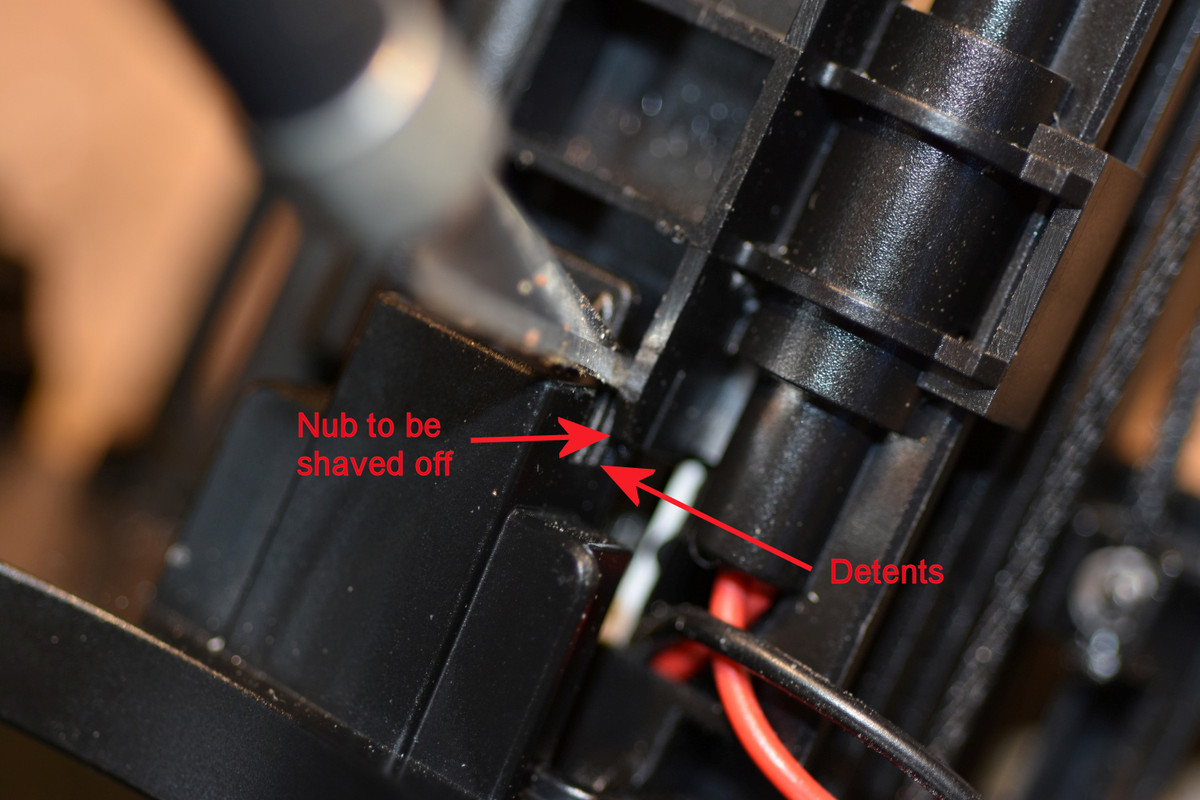 The tilt mechanism uses a standard 9gr micro servo. We already installed the mounting bracket as it is the backside of the limit switch mounting plate. Install the servo and train the cable down the back right side of the mast. The mounting plate from the Thingiverse files is designed for a servo that has it's cable coming out at the bottom of the servo. If you servo is like mine with the cable coming out the side just cut a slot in the mount in the appropriate place.  I like to use ball connectors when making up linkages as they eliminate almost all slop. I had some very small connectors that were salvaged from an old helicopter that I used here. Larger ball connectors, clevis links or even Z-bends could be used. Just try to keep the linkage as tight as possible. I mounted the bottom connector at the rear of the mast base down near the bottom as shown below. Simply drilled appropriate size hole and screwed the ball in place. 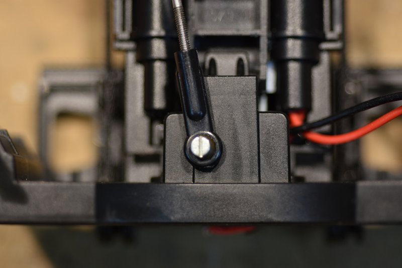 It takes very little servo arm movement to make the mast tilt back and forth. So I cut the servo arm back to one hole and installed a ball connector to the arm. Installed the arm on the servo pointing straight back after making sure the servo was centered. Measured the distance between the two connectors with the mast standing straight up and made up the appropriate length connecting rod.  Here's an overall view of the completed linkage.  The final step was to make a small clip and screw it to the mast base to hold the servo cable and lift motor leads in place. 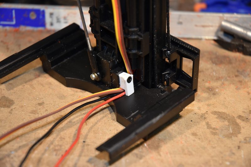 That's it! I mentioned above that it takes very little movement of the servo arm to tilt the mast back and forth and in truth the design of the mast does not allow for a lot of motion. So to prevent over stressing the tilt mechanism at it's limits I have my transmitter end points set to plus and minus 30 percent on this channel. Next post I think I'll do some body work.
|
|
#23
09-07-2021, 03:41 PM
|
|||
|
|||
|
Bruder Piggyback Forklift Build part 7
Taking a break in this post from mechanical modifications. Instead I'm going to do some body work. One of the big problems with converting this Bruder forklift to RC is of course the size. There just isn't much room in this thing for all the electronics that need to go in and not have parts sticking out all over the place. With the exception of the tilt servo I think I've been pretty successful at this up to now. One of the biggest components that needs a home is the battery. They are big and bulky. The only place in this model that a battery can realistically fit is inside the right side of the body where, on a real forklift like this, the engine would sit. Another consideration is how to charge and/or change the battery. You could, I suppose, just take the thing apart or run a charging plug to the outside somewhere. I didn't like any of those options. What is needed is a removable hatch. So happens the model has a hatch over this engine area molded in to it already. [img] 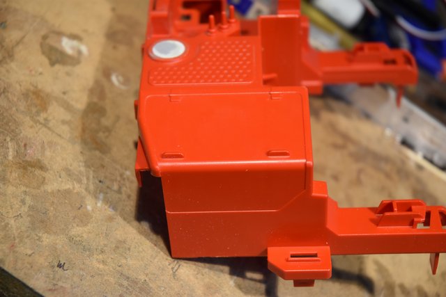 [/img] [/img]If we cut this molded hatch out it would make a pretty good sized opening that a small battery pack could be inserted. So that is what I decided to do. I wanted to minimize damage to areas around the hatch and because of all the curves in this piece I decided to use the good ole fashion method of sawing the part out with thread. For those not familiar with this technique you get a spool of just about any kind of thread, the thinner the better. Pull off a length, keep it pulled tight between your hands and just start moving the thread back and forth in a sawing motion. The friction of the thread against the plastic will cut right through. It helps to slightly pull the thread against the plastic in the direction you want to cut. Go slow, especially around the corners and you'll be surprised at how quickly plastic can be cut. With a little practice it can be quite accurate. [img] 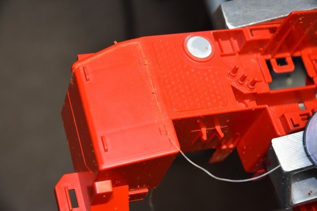 [/img] [/img]If you look back at the first photo you might think that the place to start sawing would be on the left side of the hatch where there is no body. I don't recommend this. The thread method works well but can wander just a bit when first starting a cut and I wanted to leave the corner of the body as sharp as possible. If you look back at the last photo and look carefully you'll see a very small hole I drilled near the center of the top line of the hatch. This is where I inserted the thread. I then cut back to the left and down to free that side of the hatch leaving a nice point on the end of the body. Then came back and cut out going to the right, down and finally back to the left on the bottom.. I cut right through both of the simulated hinges as I figured I was just going to sand them off anyway. Here is the hatch cut completely out. [img] 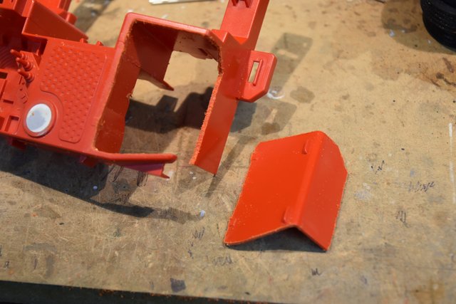 [/img] [/img]Needed some kind of support to hold a removable hatch in place. So I took some pieces of small square styrene and glued then in around the perimeter of the hole I just cut leaving about half of the plastic exposed. [img] 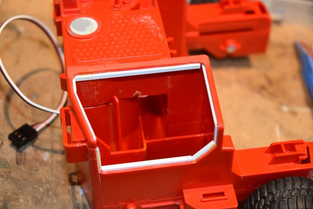 [/img] [/img]Now I need a new hatch to fill the hole. One of the Thingiverse parts is a new cover for this area. However I thought it looked to squarish and it didn't match the curves of the model so decided not to use it. I could have reused the part I cut out but would have had to spend some time gluing plastic to the edges of make up for the gap left by the thread. Even as thin as the thread is, it leaves a noticeable kerf. I decided to design and print my own. With some very careful measuring using calipers, a digital angle finder and radius gauges I came up with a design. Below is a photo with the Thingiverse cover on the right and my cover on the left. [img] 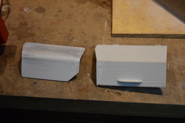 [/img] [/img]After a little sanding to tweak the fit here is the new cover sitting in place. [img] 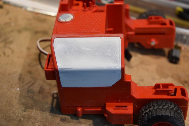 [/img] [/img]To keep the cover in place I thought about making hinges to replace the molded ones that got cut and sanded off. But because of the size needed to look right I decided that was too much work. Instead I opted to just install a couple of lugs that would fit in gaps under the top portion of the opening and use a small super magnet on the bottom to 'latch' the cover. The magnet needs something to grab so I cut a small piece of tin and glued it into a small recess cut in the bottom back side of the cover. Here is the opening for the cover with the notches cut out of the previously installed plastic supports. There is a big piece missing on the upper left because there is just not a large enough under-hang here to glue the styrene to and I couldn't get it to stay in place there. The rest is more than adequate for support. To hold the magnet in place I glued another short piece of sytrene onto the inside of the wall placed to hold the magnet at the right height and then CAd the magnet in place. [img] 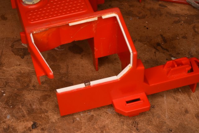 [/img] [/img]And here is the underside of the cover so you can see the lugs and tin 'magnet catch'. [img] 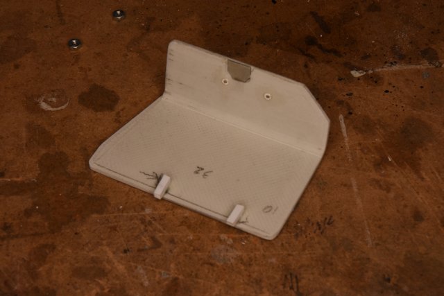 [/img] [/img]The last step was to add a handle to the cover to make it easier to open. I just bent a piece of 1/16" Plastruct plastic coated wire to a shape I liked, drilled matching holes in the cover, inserted the wire ends and glued in place with PlasicWeld. [img] 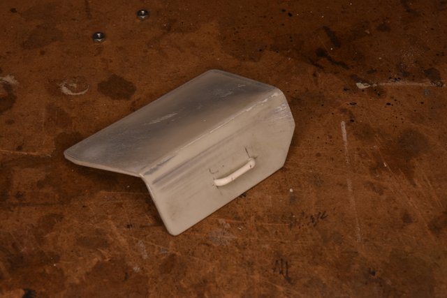 [/img] [/img]Here is a photo of the completed battery hatch cover. Of course like any 3D printed part it still needs some final filling and sanding before it will be ready for paint. [img] 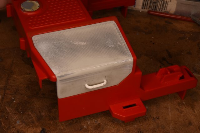 [/img] [/img]Now that the battery hatch is complete I could take some internal measurements and get an idea of exactly how big of a battery pack I could fit in. Keep in mind though that you can't use the entire space. Some room will be needed for the mechanism to move the lift mast assembly forward and backward. Which is what I will cover in the next post.
|
|
#24
09-08-2021, 02:20 PM
|
|||
|
|||
|
Bruder Piggyback Forklift Build part 8
The last mechanical assembly that needs to be installed is the servo and linkage to move the lift mast assembly in and out. The original poster of the Thingiverse conversion parts used what some refer to as a wing or aileron servo. They are designed to fit in narrow places like wings. These servos are narrower than conventional servos and have their mounting flanges sit flush and parallel to the back of the servo instead of being perpendicular to the back. He designed his servo mount accordingly. I didn't have any of these servos on hand so decided to see if I couldn't fit a standard mini servo into the same space. After some measuring I determined that I could. But how to mount it? I could make a mount similar to the Thingiverse part but with a top screw hole for one end and a second mount to attach somehow to the curved wheel well housing wall on the other end. That would be tricky and could obstruct the ability to run wires through that area later on. After studying the shape of the servo I wondered if it wouldn't be possible to make a mount that only used one screw for one end of the servo and then wrap around the round portion of the servo and keep it from moving side to side under load. After making up a couple of trial mounts I came up with the design I finally used and it seems to work well. The photo below shows the servo mount from Thingiverse on the right and my mount on the left. [img] 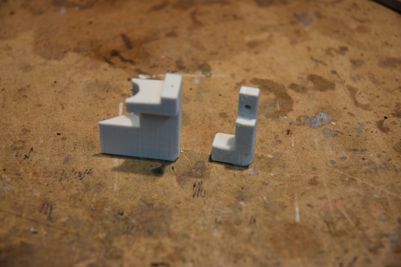 [/img] [/img]The mount fits into the lower body as shown below. [img] 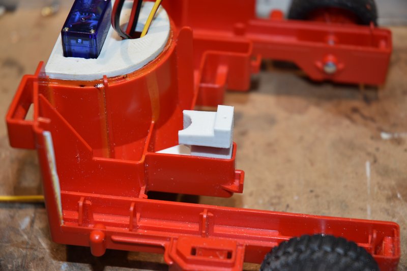 [/img] [/img]I drilled a couple of holes up through the bottom of the body and into the mount to secure it with screws. NOTE: The mount needs to be turned 180 degrees from shown for proper orientation, I wasn't paying attention when I took this photo. Also the photo shows round head screws again. Don't use them. [img] 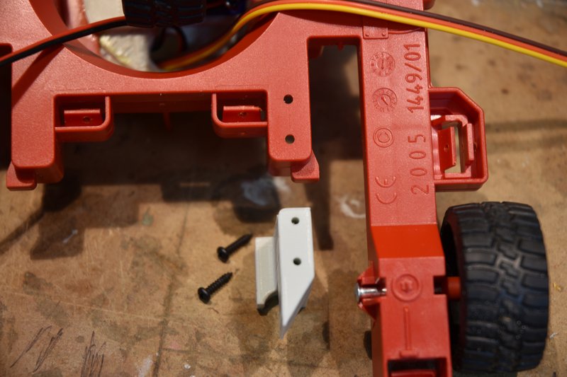 [/img] [/img]You must use flat head screws here or the lift mast assembly will not be able to slide past! Yea, after all this time I finally broke down and bought some flat head screws. ****, I bought hundreds so I won't have this problem ever again. [img] 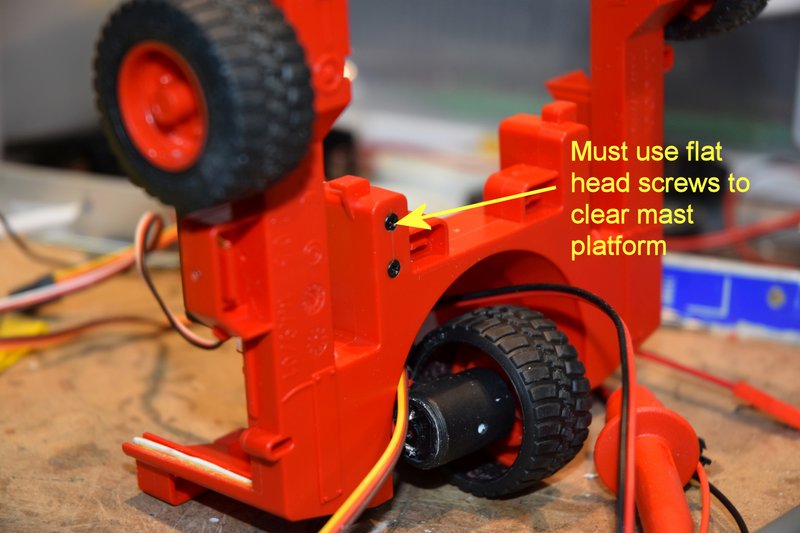 [/img] [/img]The next photo shows how the servo fits in the mount. When I first installed the servo I used a standard flanged head mounting screw that came with the servo. I found though that the flange would not clear the inside of the top body section when I tried to lower it in place. [img] 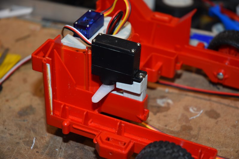 [/img] [/img]If I removed the flange or used a smaller screw I did not think the servo would be held securely enough as the mounting hole on the servo is larger than the screw so that a rubber vibration isolater can be used. Don't need the isolator in this case and I wanted the servo mounted solidly. So I cut off a short length of plastic rod and center drilled it to make a bushing to take up the excess space. [img] 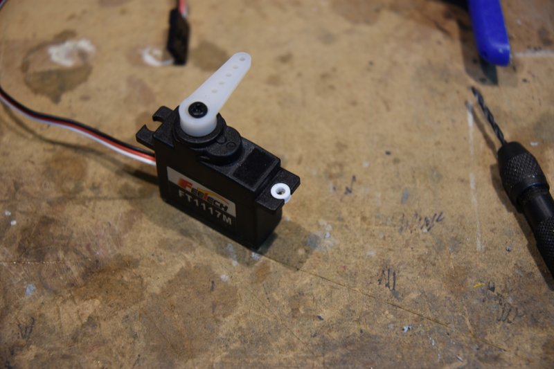 [/img] [/img]I then cut and drilled a piece of brass bar stock to use as a clamp across the entire width of the servo's mounting flange. This photo shows the final mounting. You can see that I also started to remove some of the internal plastic. [img] 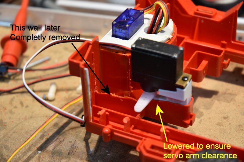 [/img] [/img]I again used ball connectors to make up the linkage between the servo and lift mast base. I used Tamiya 4mm balls and connectors just like the ones used in their truck kits. You can buy these direct from Tamiya but be aware that they refer to them as 'adjusters'. I mounted one ball on the end of the longest servo arm that came with the servo and oriented it pointing down as installed on the servo. The ball for the lift mast base was mounted as shown. Exact placement is not critical. There isn't room on the underside to install a nut so the hole I drilled for the ball was undersized and then I forced the threads to cut their way through the plastic as I installed the ball. [img] 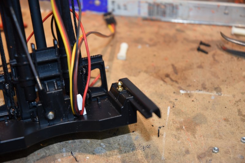 [/img] [/img]Because there was not a nut on the backside of the ball connector I was a bit concerned about it eventually working itself loose. So I mixed up a small amount of 2 part epoxy and poured it into the cavity where the screw thread was and embedded it. [img] 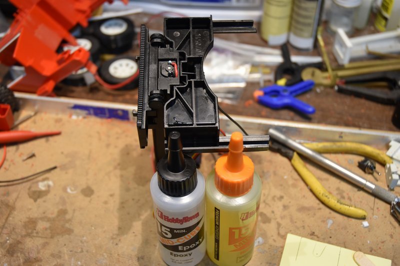 [/img] [/img]And here is the linkage to connect the two balls together. Note that I cut the threaded ends of the connectors back a bit. I did this to make it a bit easier to make length adjustments if needed without having a lot of friction to fight. [img] 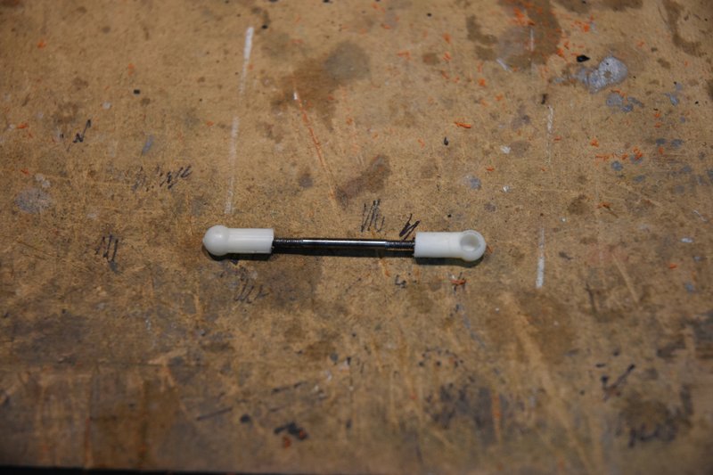 [/img] [/img]And that's pretty much it. In this photo you can see how the servo fits inside the body. There is still quite a bit of room left for a battery pack. In this photo the servo is shown in its neutral position. [img] 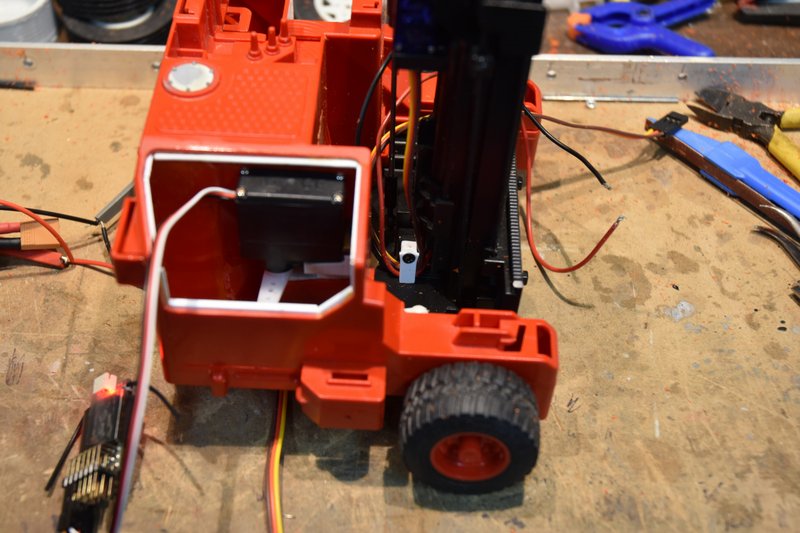 [/img] [/img]Like the steering servo, I needed more servo arm movement than the standard 90 degree left/right. One option would be to install a longer servo arm but that might start causing clearance problems. Or I could install resistors in the servo to increase it's range. Maybe a little easier to do in a mini servo as opposed to a micro servo but not what I wanted to do. Again I was able to open up the set points on my transmitter for this channel to 150%. That gave me enough linkage movement to be satisfactory. This photo shows the mast in it's full forward position. [img] 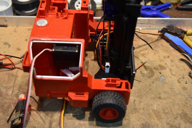 [/img] [/img]The mast assembly could be moved forward a bit more but as long as the back side of the forks would clear the front of the body I was satisfied. You can see that the mast itself is now in front of the center of the front wheels. Those wheels are the fulcrum for a lever and the further ahead the mast gets the easier it becomes to tip the forklift over. This last photo shows the mast fully retracted. [img] 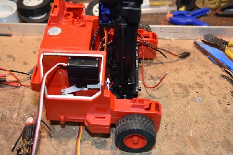 [/img] [/img]Again the mast assembly has room to move back a bit more. But some room is needed at the back of the mast base to allow the tilt servo cable and lift motor wires room to move. I may, after more operational experience, shorten up the link rod between the servo and the base plate. This would shift the entire lift mast assembly backwards. I have more front extension then really needed and it would move the mast further behind the front wheels increasing the amount of weight that could be lifted without tipping. We'll see. That is all the mechanical adaptations that need to be made to make this model operational. In the next post I will address two other small items before we get into how to stuff 10 pounds of electronics into a 5 pound sack.
|
|
#25
09-09-2021, 02:03 PM
|
|||
|
|||
|
Bruder Piggyback Forklift Build part 9
A couple of things to take care of before tackling the electronics. First, if you look back at the last few photos in the last post you see the open area in the body where the battery pack needs to go. You also see that there is the servo and linkage that moves the lift mast assembly in and out. We don't want the battery to hit or obstruct this linkage. So some kind of barrier needs to be made and installed to prevent this. I choose again to use brass but plastic or even wood could be used here as well. I measured the height from the inside bottom of the lower body to the top of the nut holding the ball connector on the servo arm and added 1mm. I just dug out some scrap square tubing and flat plate from my scrap box, cut to size and soldered up the parts as shown below. [img] 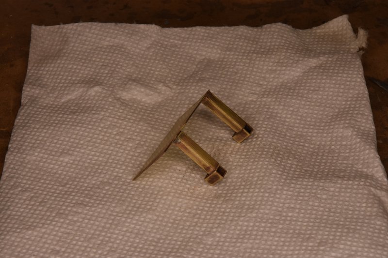 [/img] [/img]The piece fits into the lower body as shown. The 'feet' on the bottom were sized to fit between the outside wall and a rib in the bottom. [img] 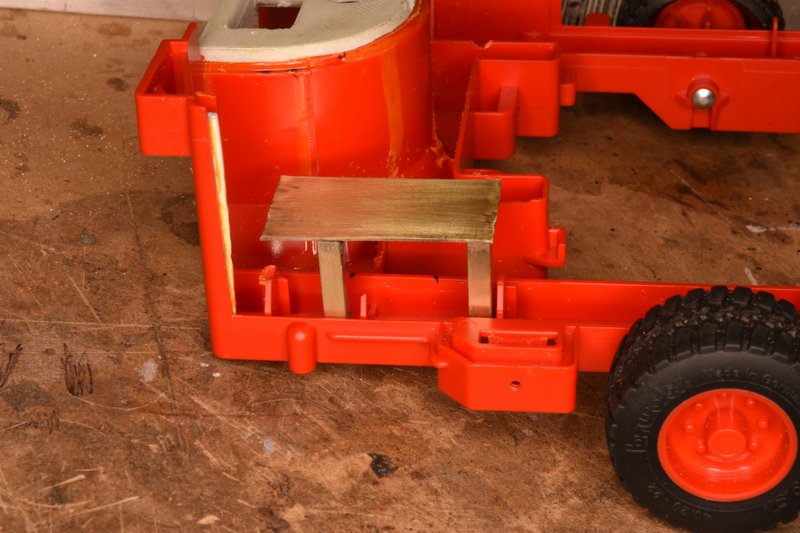 [/img] [/img]Here's another view from a different angle so you can see a little better how the feet fit in. They were drilled for #2 screws and matching holes drilled in the bottom of body. [img]  [/img] [/img]And here's a view of the bottom showing the mounting screws. Yep, flat head screws now, I finally learned although it doesn't really matter here as there is nothing that needs to move past these screws. [img]  [/img] [/img]I actually did this part of the build early on which you might be able to tell from the photos. I did this so I could get a better ideal of just how big a battery pack I would be able to fit in. I had originally planned on using a 3S lipo. However the quality of the small ESCs that would work on 3S I discovered are horrible. They either have no real low voltage range to them or they blow out after a few seconds. They all come from China and they must all be made by the same company as it doesn't matter who you get them from they all look alike. I finally decided to try 2S battery and ESCs. This worked much better. I found some ESCs that claimed to be a new design and had a big capacitor hanging off one end. So far they have worked and held up well. The battery I finally settled on is made by a company called SPC Maker. It is 2S and rated 500mAh. It is primarily marketed to the racing drone group. It measures approximately 50x25x13mm and fit in the available space very nicely. And while it looks awfully tiny compared to the size of the batteries we normally use in our trucks and construction equipment I find that I can get a good solid hour of continuous operation out of it, which is plenty for me. The last thing to be addressed before assembling all the RC electronics is the warning light on top of the ROPs. I didn't put any other working lights on my model but I did want that light to flash. This is a real simple conversion. I used a LED that had it's flashing circuit already built it. These are available from a number of sources, mine came from Eflite. It also included the necessary over-current protection resistor already installed. Photo below shows the light fixture and the LED. [img] 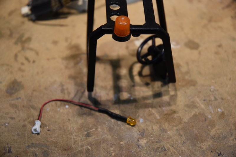 [/img] [/img]I cut the socket fitting on the end of the wire off so I could add additional wire to the LED. Also if I had left it on I would have had to cut a much larger hole in the body to pass it through to the inside. To remove the lens, just grab it and twist while pulling up. Mine came right off. Drill a 3mm hole right through the middle of the circle as shown. [img]  [/img] [/img]There is a lug in the center of the lens that needs to be cut back some so it will sit down on top of the LED. Don't remove it completely as it will act as a light pipe make the lens appear brighter when the LED is lit. [img]  [/img] [/img]I glued the LED into it's mounting hole from the bottom using CA. After it cured I then bent the wire to follow the inside of the ROPs cage and CAd it in place. [img]  [/img] [/img]Then the lens was glued back in place over the LED. To prevent possible fogging of the lens from CA I used a watch crystal cement. The last step was to hold the ROPs in postion on the upper body and mark the location of the notch for the wires from the LED to enter the body. [img]  [/img] [/img]I crimped a couple of female connector pins to the ends of the LED wires. When installed these will just plug onto the positive and negative pins of the battery port on the receiver. When the receiver is powered up from the BEC of one of the ESCs it will also turn on the flashing LED. At this time all the modifications are pretty much complete. I had tested each individual servo and motor system as it was installed. Now everything was hooked up and run though it's paces. I was very relieved to find that everything worked as it should. The model was stripped back down and sent to paint. I won't bother with showing any of that, painting is painting. Next post I'll start in on the 3d version of Tetris and figure out how to cram everything into the available space.
|
|
#26
09-10-2021, 09:12 AM
|
||||
|
||||
|
That fork is really coming out awesome!!! I can't wait to see some videos in action, or see what kind of cargo you come up with!
If you want an LED to fill out a light better, fill the lens area with clear Hotglue, and assemble it while still hot. It evens out the light instead of being a focused point.
__________________
What do ya mean "Cars are neither Trucks or Construction"? It's still scale, and i play fairly well with others, most of the time...
|
|
#27
09-11-2021, 01:32 PM
|
|||
|
|||
|
Quote:
|
|
#28
09-11-2021, 01:46 PM
|
|||
|
|||
|
Bruder Piggyback Forklift Build part 10
I'm going to split the installation of all the electronics into two parts. In this post I'll show all the components I used and some modifications. In the next I'll go over the actual installation.. At the end of the last post I mentioned that I hooked everything up and tested to make sure that after all the putting together and taking apart that it would all work properly. This photo shows everything laid out on a table and temporarily wired up as I tested. [img] 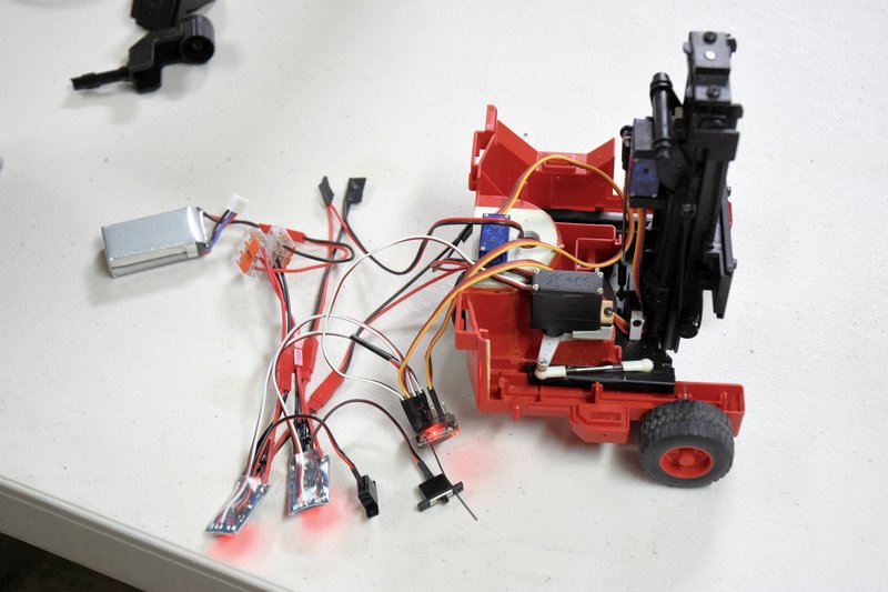 [/img] [/img]Man, what a mess of spaghetti. In this photo you see the following parts: 1 battery pack, 2 ESCs, 1 6-channel receiver, 4 JST connectors, and next to the battery pack a pair of 3 terminal WAGO connectors. Will it all fit? This is the battery I ultimately ended up using. While 500mAh doesn't sound like much capacity I have found in use that I can easily get a good solid hour of continuous run time out of it. And it fits easily into the space available. I purchased this particular battery from https://www.buddyrc.com They are an online only RC hobby store located in Columbus, OH. They primarily deal with the airplane/drone crowd but what hobby store doesn't. BTW, if you are looking for a RadioMaster transmitter they are dealers and also carry a wide array of spare parts. [img]  [/img] [/img]This is the receiver I used in this build. It is a 6-channel DSM compatible unit so it will work with almost any Spektrum radio as well as Open TX radios such as the RadioMaster. This receiver is the smallest 6-channel one that I know of that will take standard servo connectors. The only ones smaller use soldered connections instead of plugs. These receivers also have the advantage of being relatively inexpensive. This one is a bare bones model by which I mean it doesn't have telemetering or a diverity or duplex antenna. I purchased this from BuddyRC also. Be aware if you shop for one of these they come in two basic versions. The one shown is the 'top' connected version. They also make it in an 'end' connected version which is going to be about 1/4" longer and you would also need extra room at the end for the plugs. [img]  [/img] [/img]This next photo shows one of the ESCs I ended up using. These are 2S, 10A rated units. They have a 1A BEC and no braking. I originally wanted to go with 3S ESCs but couldn't find any that worked properly or that didn't let the magic smoke out after a few seconds. I really wish there was a source of US made ESCs. These were obtained on Ebay. They are all made in China so I don't think it really matters much which vendor you pick, I'd just look for one who states they ship from within the US. On the right side you can see a large capacitor extending out from the circuit board. This is apparently a new design, and so far, mine have worked well. [img] 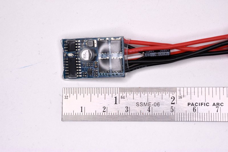 [/img] [/img]I made a few modifications to these ESCs. They came with a switch attached to wire leads to turn the ESC on and off. Since I was going to use a master switch I didn't need the attached switches. And I especially didn't need two switches. To remove the switches I had to remove the plastic heat shrink that had been put on by the factory. Just use a sharp knife and pare down along one edge of the circuit board and peel off. [img]  [/img] [/img]Then using a small soldering iron I heated up each blob of solder on the circuit board at each switch wire location on the lower right as shown. When each blob melts just pull the wire free. Don't remove the little blobs of solder. [img]  [/img] [/img]Without the switch there is no way to turn the ESC on. Simple fix, just solder a small jumper across the two pads where the switch wires used to be. I just used a small piece of wire snipped from a resistor. The blobs of solder left behind from removing the switch wires should be enough. [img] 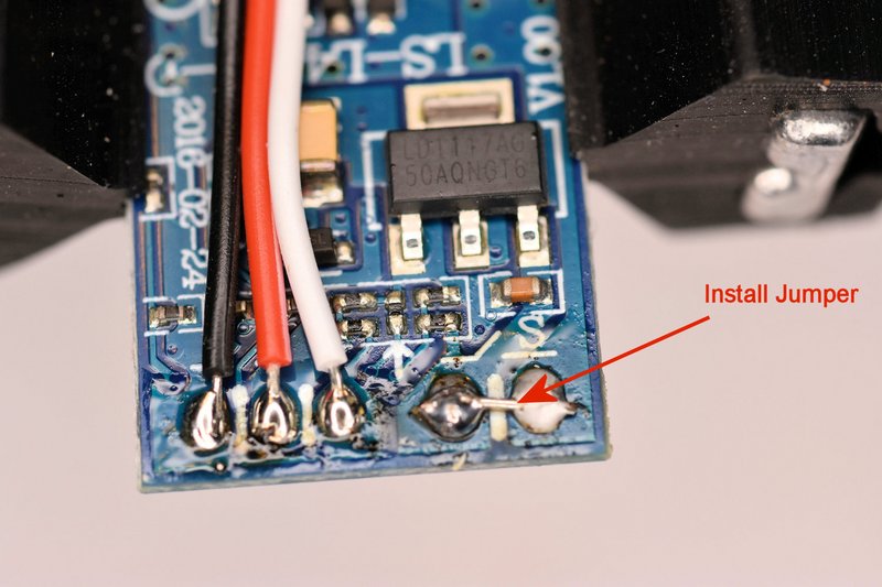 [/img] [/img]These ESCs are going to be mounted in a plastic body and all the wires on and around them will be insulated. But I still felt it wouldn't hurt any to re-insulate the boards. You could put heat shrink back on like they had originally but I decided to wrap them in Kapton tape. Kapton tape is very thin, very strong and has a very high dielectric or insulting rating. It's also not cheap. But I had a lot left lying around from my early 3D printing days when we used to put Kapton on the build platforms as a surface for the print to stick to. I primarily used it because it was a lot thinner than the heat shrink and I wanted all the spare room I could get. [img]  [/img] [/img]Since I had two ESCs that were going to be connected to the same receiver the last modification was to remove the red + wire from one of the servos so the receiver would only get power from one ESC. So, next post I'll finally get to what most of you have been wanting to see. How I put it all the electronics inside the body of the fork lift.
|
|
#29
09-12-2021, 01:07 PM
|
|||
|
|||
|
Bruder Piggyback Forklift Build part 11
OK, time to finish this up. Will everything fit inside. Of course, didn't you see my first post? There was some trial and error involved in deciding where to put the components but it actually was easier than I was afraid it would be when I started this conversion. There were a few snags and I'll point them out so you can avoid them. The first step was to lay in a length of two conductor cable for the battery power supply as shown. It has a JST connector on one end and is longer than anticipated and will be cut to final length later. The red wire will go to the master switch under the operators seat and the black wire will actually get pulled back about to the center of the wheel housing for the negative return to the battery. [img] 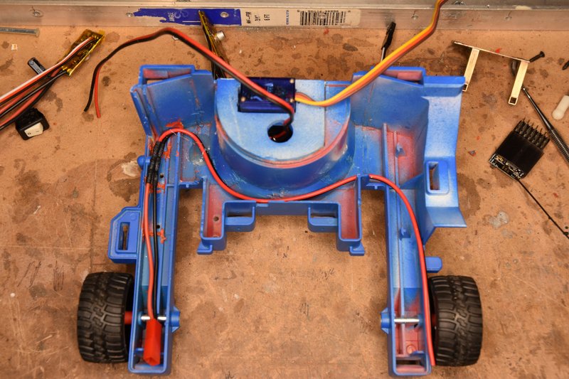 [/img] [/img]The first component I mounted was the ESC for the drive motor. I simply hot glued the ESC to the back right side of the rear wheel housing as shown below. The large capacitor on top was just pushed over so it laid on top of the wheel housing. [img] 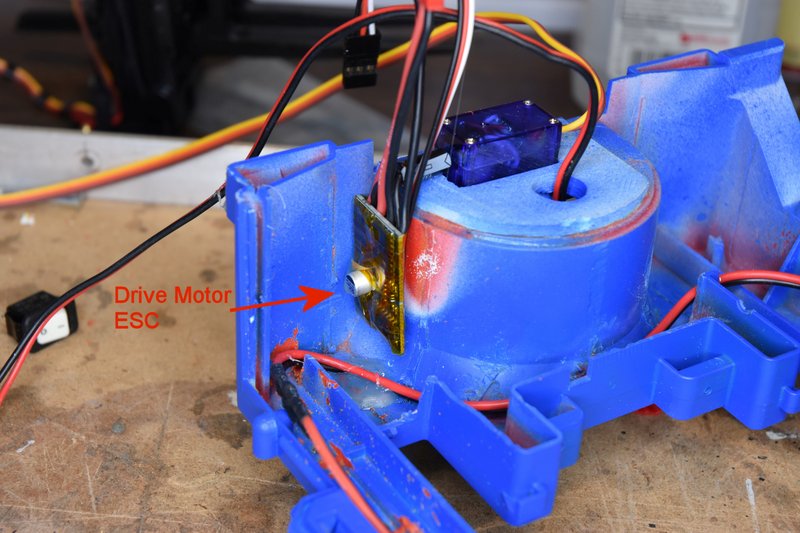 [/img] [/img]So logically the second ESC for the lift motor should go on the other side of the wheel housing. So that's where I mounted it and again bent the capacitor over to lay on the wheel housing. [img] 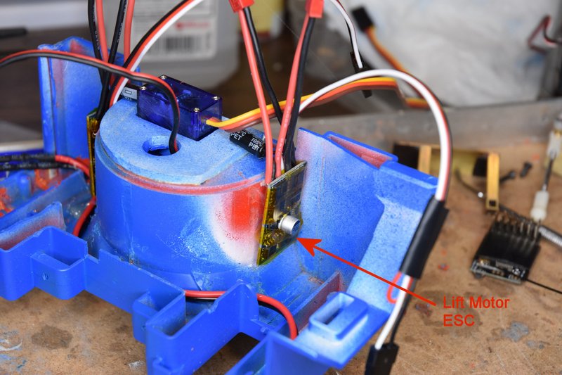 [/img] [/img]Using a piece of servo tape I mounted the receiver in the position shown. I placed the terminals for the servos on top so they would be easy to get to and figured that would give me room underneath to coil up excess servo lead. I bent the antenna wire to run along the side of the left wheel arm and taped it in position. [img] 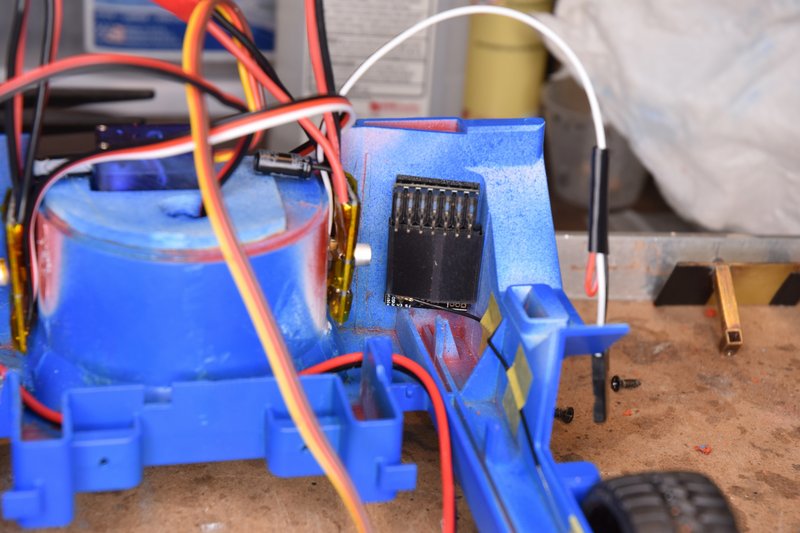 [/img] [/img]SNAG #1 - If you have been following this build and seen the 3D printed parts I've used from Thingiverse, have you wondered why the steering servo mount is straight instead of curved on the left side? It' because part of the top body section hangs down over the left side of the wheel housing in this area and there isn't enough clearance for the printed part. I tried assembling the top and bottom body sections together at this time to check fits and clearances and found that the capacitor on the lift motor ESC would not fit. If fact none of the wires sticking up from the ESC would fit. I think I got so used to just working on the lower body section that I forgot about this clearance issue. So after some study I removed the ESC and remounted it to the position shown below. I also mounted it lower so the wires wouldn't get in a bind with the top part of the model and bent the capacitor leads down over the front of the circuit board. [img] 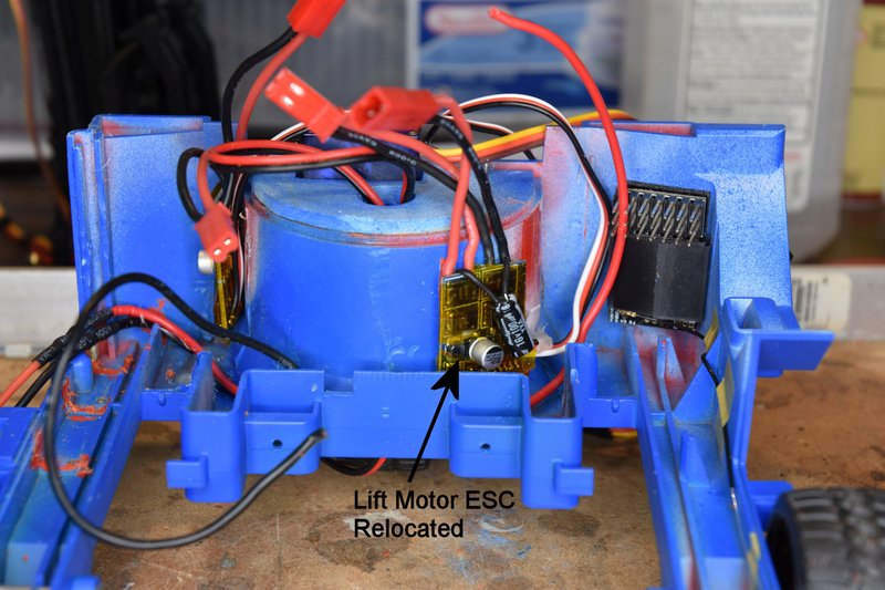 [/img] [/img]Next I mounted the master switch into the hole made previously in the top body section. In this photo I had placed the top body back into position to check clearance from the back of the switch to the receiver. Good reason for removing the drivers seat. [img] 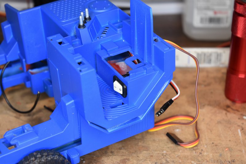 [/img] [/img]I wanted to be able to completely separate the top body from the bottom for maintenance and repair work if ever needed. So I installed a XT30 connector as you see. I used this connector because it was the smallest two conductor connector like this I had on hand. The JST connectors are longer when assembled and I though they might get in the way. While the XT30 works I now wish I had taken the time to find something smaller. This doesn't need to be a polarized connector either. The switch is just in series with the positive battery lead. You can also see the second red wire added to go from the switch back to about the center of the wheel housing. [img] 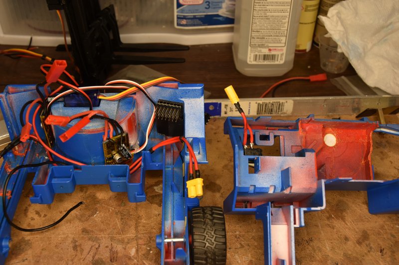 [/img] [/img]I had wanted to use the WAGO connectors to make the power connections. I really like those things but they were just a little too big to fit in the space between the front of the wheel housing and the front wall of the lift. I could have maybe put them at the bottom backside of the lift but would have then had to splice extra wire to the ESCs. Didn't feel like doing that much extra work. So I simply twisted the ends of the black wires and red wires together and soldered them. Then insulated the ends with a piece of heat shrink and a little tape. These wires are a little stiff so I held them in place with a couple dabs of hot glue. [img] 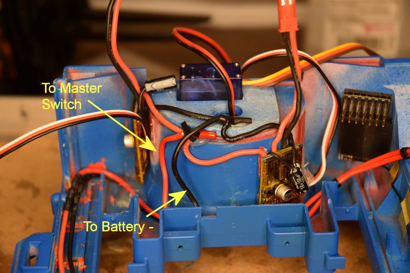 [/img] [/img]Reinstalled the mast platform retraction servo. [img] 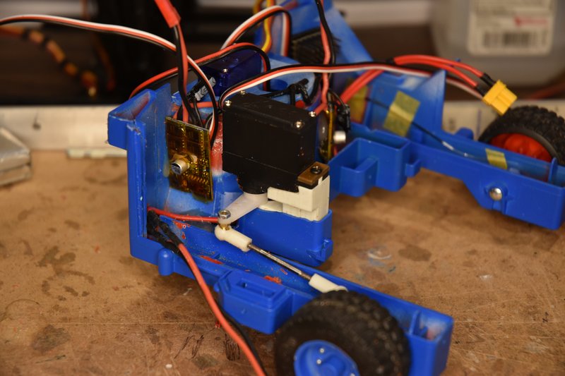 [/img] [/img]Followed by the battery platform. I covered the edges of the platform with a couple of layers to electrical tape to protect the wires from possible cutting. [img] 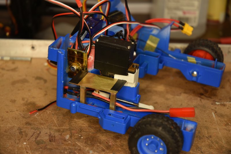 [/img] [/img]Next was to cut to length and splice the power leads from the drive motor to it's ESC. Solder and heat shrink tube to insulate. [img] 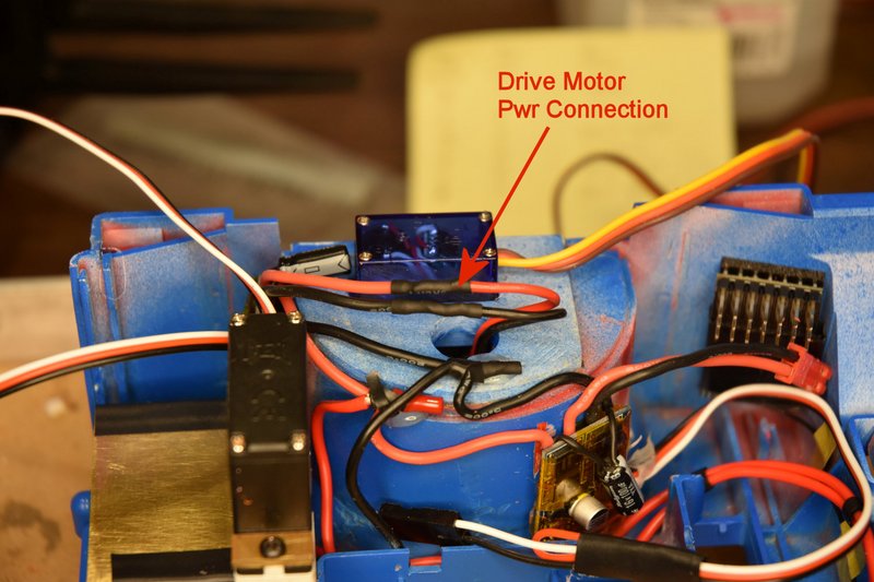 [/img] [/img]I then wrapped narrow pieces of tape around the tilt servo leads and lift motor wires on the mast assembly to bundle them together. Place the mast assembly back into place on the lower body and connect the servo linkage. [img] 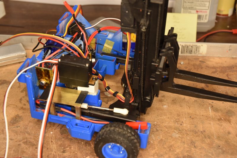 [/img] [/img]Then the lift motor leads and and ESC leads were trimmed to length, spliced and heat shrink. [img] 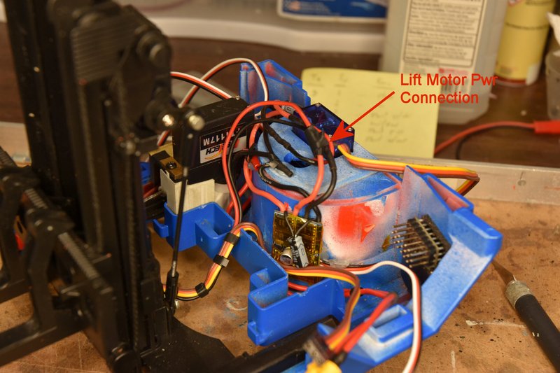 [/img] [/img]Next is to run the servo and ESC control cables to the receiver. I won't show all of these being run. I ran the cables from the drive ESC steering servo and mast retraction servo across the top of the wheel housing to the receiver. The lift motor ESC and tilt servo cables were run across on the bottom of the body to the receiver. Each cable needed to be shortened to some degree so I wouldn't have a huge mass of wires under the receiver. So I ran one cable at a time starting with which ever cable I had assigned to channel 6 on the receiver. And then channel 5 and so on. I'm not using channel 2 so it's open as well as the battery port since power is coming from the drive motor ESC. [img] 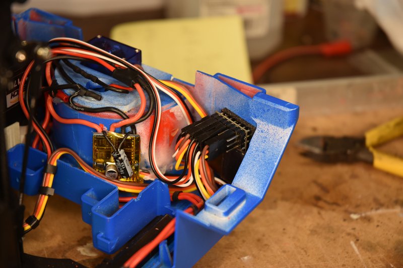 [/img] [/img]OK, as usual the web site is telling me I talk to much. Have to break this post here and will continue in the next.
|
|
#30
09-12-2021, 01:15 PM
|
|||
|
|||
|
Bruder Piggyback Forklift Build Part 11b
(continued from previous post) Ran the leads of the warning light on the ROPs through the notch cut earlier in the top part of the body and reinstall the ROPs. [img] 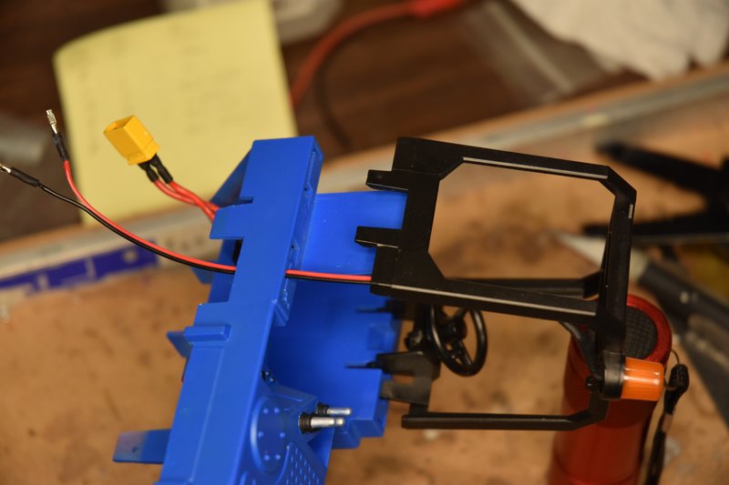 [/img] [/img]In this photo you can see how the leads to the warning light plug onto the positive and negative pins on the battery port of the receiver. This allows me to completely separate the top and bottom body parts if ever needed. [img] 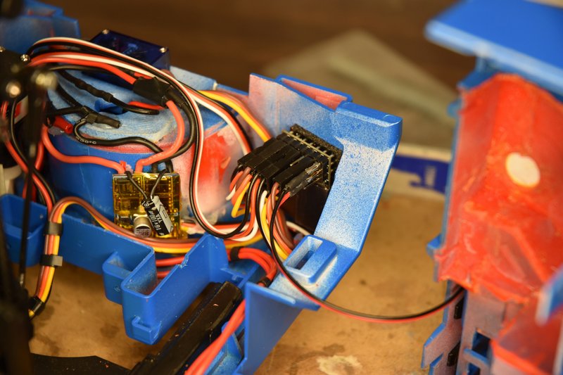 [/img] [/img]plug the switch leads back together. [img] 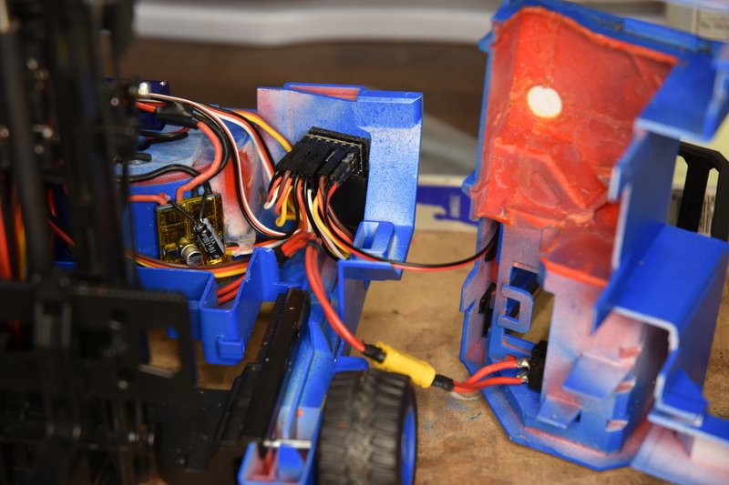 [/img] [/img]Install the battery and plug it in. [img] 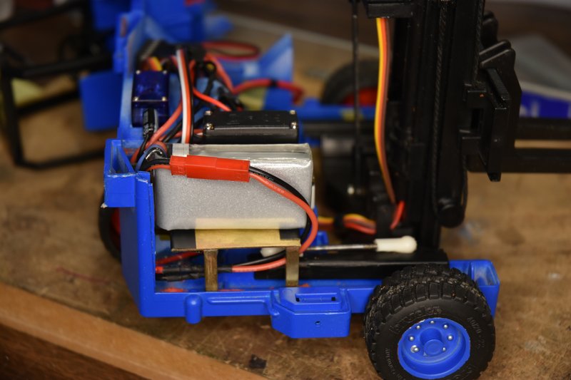 [/img] [/img]Turn on the transmitter and then flip the master switch and see if everything is going to function. Hooray, Success, let's button this thing up. SNAG #2 - I started to put the top body section in place and ran into a problem. The right hand side would go together just fine but something was keeping the left hand side from closing, not even close. A quick look down the hole under the drivers seat showed what the problem was. When I checked the clearance between the back of the switch and the receiver earlier the servo leads were not connected. I thought I had enough clearance but because of the size of the XT30 connector I was binding on those servo leads. What to do after I was so close to being done? After a little thought the fix was simple. Pried the receiver off the double sided servo tape and scrapped the tape off the inside of the body. Man that stuff sticks! I then turned the receiver 90 degrees counter-clockwise, moved it over towards the wheel housing and pushed it downward as much as it would go. plenty of clearance. And sorry, but I didn't think to take a photo at this time showing this but if you look at the photo above showing the receiver with everything plugged in and visualize it turned on it's side you'll get the idea. plenty of clearance for the switch connector now. Alright, put the top back in place, line it up and push it home and , wait, what??? Everything fits except the very back end won't quite go together. Oh for the love of.... SNAG #3 - Remember the clearance problem I talked about above that forced me to relocate one of the ESCs? Well turns out there's even less room between the top and bottom parts than I thought. I have 3 servo cables lying across that area and they are each only about 1.25mm thick. Apparently there is not even that much room as the cables were keeping the top slightly raised. I could have just squeezed the top and bottom together but I didn't want to put the wires under that kind of pressure. I could have rerun them around the front of the wheel housing but was concerned about generating noise by running more wires that close to an ESC. The fix is simple but frustrating. Very carefully thin the top and bottom body parts in the area where the clearance issue exists. The next two photos show the areas that are the problem and need to be thinned. [img] 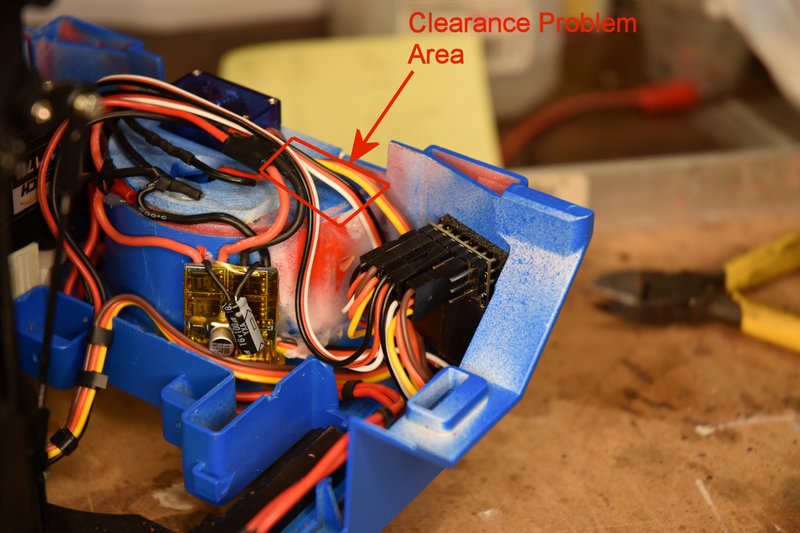 [/img] [/img][img] 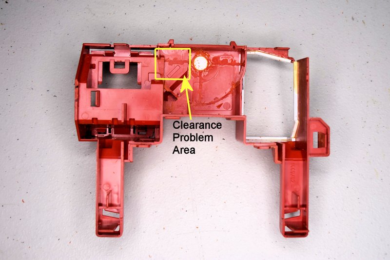 [/img] [/img]Pulling the servo cables off the receiver and moving them out of the way I started thinning by first using a motor-tool on the steering mount to bring the thickness on the left of the steering servo down to match the original body. This can be on a taper. Be careful not to grind the back edge of the part as that will show on the outside. Then using a flat riffler and sanding sticks I slowly thinned the top and bottom bodies in the areas shown above. Taking a little bit off, try the fit, take a little more, etc. until the top and bottom came together. I then rounded the sharp edges where the servo cables ran to minimize stress on them. Fortunately There was plenty of plastic left So I don't feel there is a breaking or cracking hazard. But be careful if using a motor-tool so you don't cut through the body. You only need about 1.5mm clearance in this area. If you build one of these fork lifts following my process, I would remove the material in this area back when I cut away all the other plastic that has to be removed. An easy way to measure the clearance would be to put a small ball of clay or similar material between the two halves before putting them together and then measuring the height of the squished ball. So, did it finally go together? Yes, hallelujah, success at last! One final step, install the operator's seat. [img] 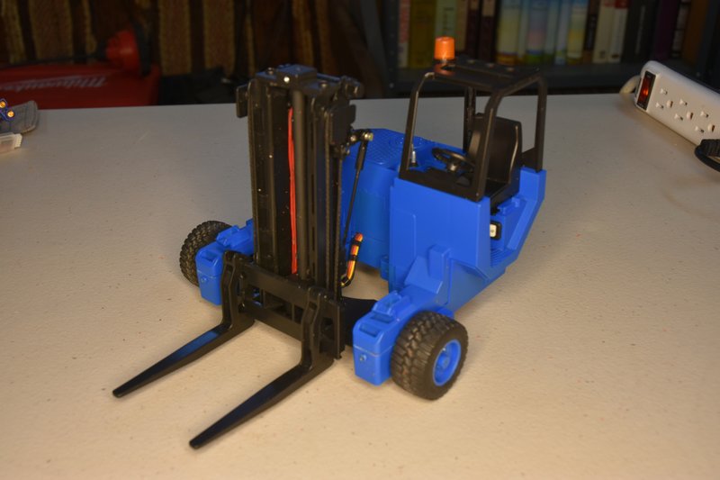 [/img] [/img]This was an incredibly fun conversion and I am very pleased with how it turned out. Took some experimenting, some designing, some fabrication and a lot of just looking and thinking. Everything I love about this hobby. If you decide you want to do one of these conversions please post up your results, especially if you do something different. Feel free to add it to this thread if you want. More than one way to skin a cat. Speaking of which, have you noticed how many different ways people have come up with to convert the Bruder D5? Now I've got to figure out how to modify the back of my flatbed trailer so I can haul this thing down the road.
|
|
#31
09-12-2021, 09:43 PM
|
||||
|
||||
|
That came out awesome!
Oh yeah, always gotta love those hidden clearance problems between halves, that don't show up until the end, so you've gotta strip it all back down to fix it.
__________________
What do ya mean "Cars are neither Trucks or Construction"? It's still scale, and i play fairly well with others, most of the time...
|
|
#32
09-20-2021, 04:25 PM
|
|||
|
|||
|
Beautiful work! And a fun toy, err, project =))
If you have a minute, I'd be obliged if you could post up dimensions of the thing (not counting the forks.) I'm curious how it compares to my wildly mis-scaled scratch build. I suspect the Bruder is smaller, which as discussed gives one all kinds of engineering challenges. -- A
__________________
I mean, how hard can it be?
|
|
#33
09-20-2021, 06:41 PM
|
|||
|
|||
|
Thanks, was a very fun build.
Front to back of body is 4-3/4 in. Outside tire to outside tire is 6-3/4in. Ground to top of body is 3-1/4 in. Ground to top of ROPs is 5-1/2 in. Ground to top of fully raised mast is 8-3/4 in. Tires are 1-5/8 in diameter. Bruder toys are nominally considered to be 1:16 scale. However I have some 4'x4' pallets and oil drums accurately scaled to 1:14 and they fit perfectly between the front legs just like they would on a life-sized machine. So who's to say what scale it really is.
|
|
#34
09-22-2021, 02:07 PM
|
|||
|
|||
|
Holy carp, okay, that's insane then that you got all that in there!
My "1:10ish" is about twice the size of the Bruder. I sized it so that it would lift onto the bed of my trailers, and some fudging may have occurred =)) Certainly makes it easier to fit the electromechanical stuff though. Thanks and kudos again. -- A
__________________
I mean, how hard can it be?
|
|
#35
05-17-2022, 03:59 PM
|
|||
|
|||
|
UPDATE
The forklift has worked well since I posted this build. There were a couple of issues though that I felt needed to be addressed. First, when I put this together I felt that I should have both the forward / reverse travel and the steering on the left stick leaving the right stick solely for up/down mast movement. This hasn't really worked out. At very slow travel speeds while trying to line the forks up with the intended load it was very difficult to not accidently knock the steering too far one way or another. So I decided I would be better off moving the steering over to the right hand stick. Not a big deal, just have to open up the body and swap a servo lead from one channel on the receiver to another. I wasn't really wanting to open this model up just for this though as it is a bit tricky getting everything lined back up to get it back together. But if I was going to open up the model I may as well try and take care of the second issue also. The second Issue, as I noted above in the original build articles, is that this forklift is very light and simply cannot lift a heavy load without tipping over. That's fine, I realized this from the beginning and only wanted to to be able to lift a scale pallet with four oil drums as the heaviest load it would have to handle. But even as light weight as this load was, when the lift mast was in it's full forward position it would take enough weight off the rear drive wheel that it often could not get enough traction to move the forklift depending on the surface. Really needed to add some weight to the back of this model. I had earlier added some lead shot to the inside of the Bruder rear tire but it just wasn't enough extra weight. So I started looking for some additional weight that I could add into the available space. If you look back at the earlier photos you can see there just isn't much room left inside. So the weight needed to be heavy for it's size and thin. What I finally came up with was a self-adhesive lead tape that golfers use to add weight to the heads of their clubs. I'm not a golfer so I didn't know this stuff existed. It's great for this purpose as it's only about a 1/16th of an inch thick, very pliable and easy to cut to any shape needed. Attached are a few photos showing where I put the lead tape in the rear of the forklift. Basically a piece was attached to most every open flat space that could be easily reached. On the tape mounted behind the receiver I did also put some electrical tape over it as the servo pins on the receiver I used are exposed on the rear and I didn't want to risk a possible short circuit sometime down the road. On the right rear side there isn't a lot of space so I put two layers of the lead tape there. I didn't weigh the tape so I don't know exactly how much weight I added but It was enough that the drive wheel now stays firmly in contact with the ground with the loads that I use. I also now have much better control of driving and steering. I took the forklift to the Indianapolis meet in April and it performed very well. Underside of top half of model: [img} 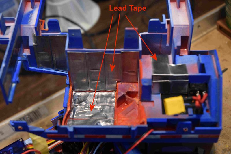 {/img} {/img}Bottom left showing tape installed behind receiver: [img}  [/img} [/img}Bottom right side: [img}  [/img} [/img}
|
|
#36
05-17-2022, 06:50 PM
|
||||
|
||||
|
How much does it feel like splitting Drive and Steer helps with the control?
With my fork i'd wondered about setting up some switched dual-rates for the throttle channel so i could switch between "travel across warehouse'' speed and "do not knock over a rack" speed Great find on the golfer lead tape! That looks like a great solution There was an rc meet in Indianapolis in April???
__________________
What do ya mean "Cars are neither Trucks or Construction"? It's still scale, and i play fairly well with others, most of the time...
|
|
#38
05-18-2022, 06:38 PM
|
|||
|
|||
|
Quote:
Quote:
|
|
| Currently Active Users Viewing This Thread: 2 (0 members and 2 guests) | |
|
|


 Linear Mode

