|
|||||||
| Construction Equipment Tech Hydraulics, Electronics, General Engineering, ect in constr equip |
 |
|
|
Thread Tools | Display Modes |
|
|
|
#1
 03-17-2011, 04:16 PM
|
||||
|
||||
|
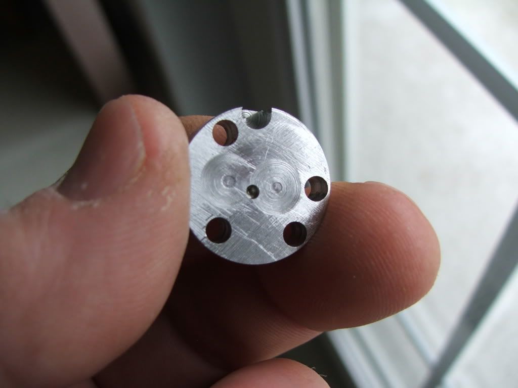
I've got the pump back that I put the new seals in to do an auto cad drawing for the gear side shims. I'll try and get some pictures of the way the face looks inside the pump and they way the gears are worn on the end of the teeth. You would probably would never notice a loss in pressure, because I'm sure if you kept closing the pressure relief valve this pump would keep going up till it stalled the motor and that just the way a gear pump is. That why they burn out the motors on the UMS pumps because when you hit the end of stroke it's full stall. I'm sure if they had a PR they would be fine. Inside it's the same as the other pump but they use bronze gears instead, so you don't see the same scratch marks. With the side area of the gear greater than the width, higher pressure forces the gear tighter to the face causing the damage and the aluminum shavings in the oil.
Rob 
|
|
#2
03-17-2011, 05:53 PM
|
||||
|
||||
|
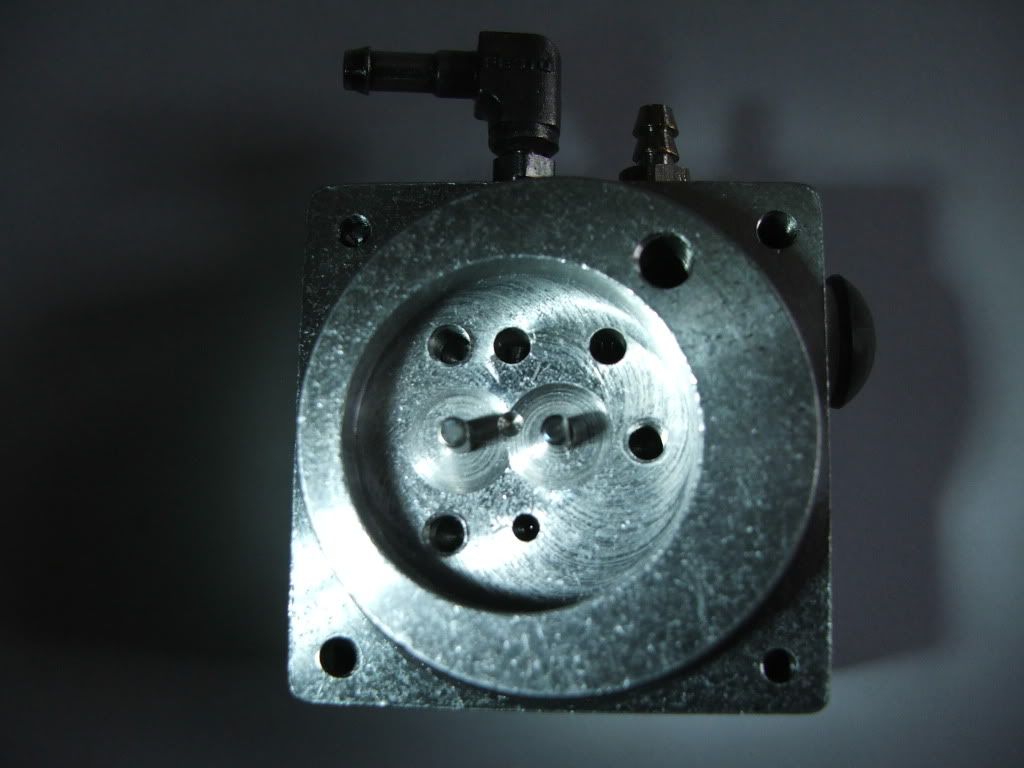
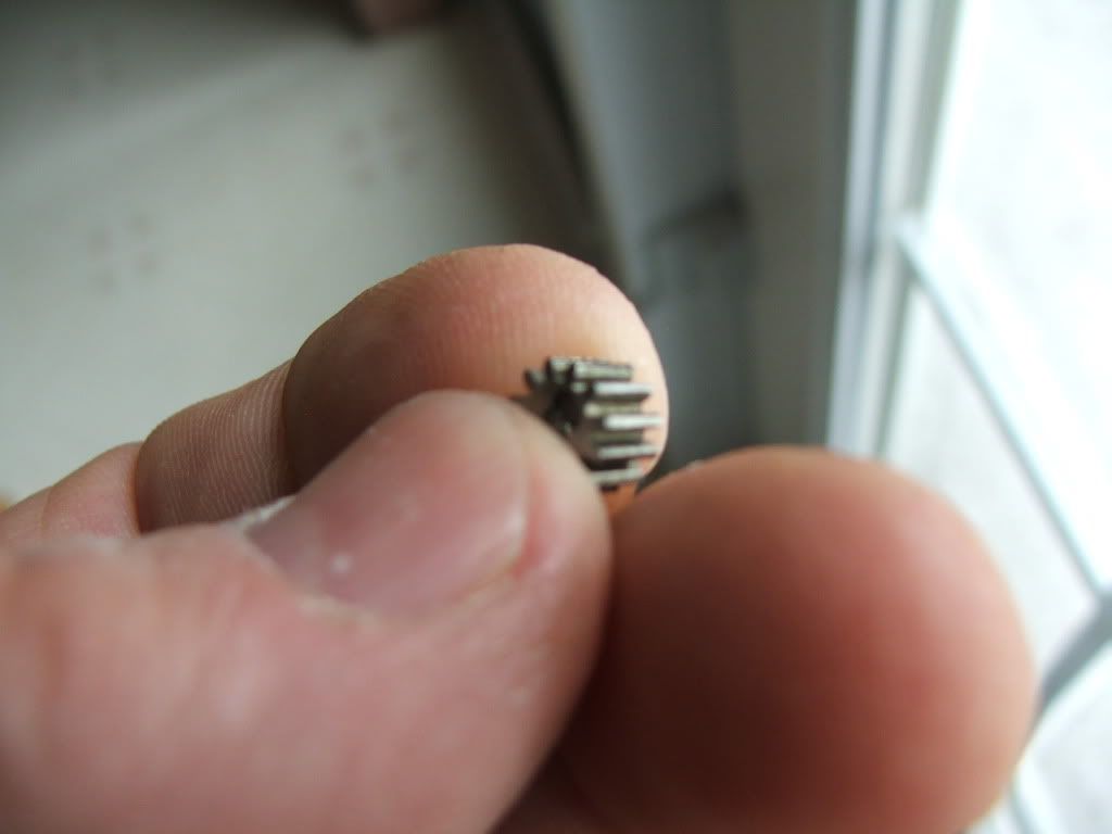
Have some pictures of the body head and gears of this pump. You'll see what I mean from the gear side pressure and it's about .010 deep. The one with the deepest undercut is the driven one. Picture of the gear was hard to focus on but you can see the curl on the trailing edge of the gear. Don't know if that is wear or pressure build up between the gears. If they're not made right and the mesh is too tight, they build pressure just coming together, IE trapped oil. These are good pumps and I think with a few changes they could be made better.
   Rob
|
|
| Currently Active Users Viewing This Thread: 1 (0 members and 1 guests) | |
|
|


 Hybrid Mode
